Address:
Shenzhen Bao'an District Xinqiao Subdistrict Huangpu Community Huangpu East Ring Road No. 504 Shenzhen Yuan Industrial City Building C
Work Hours:
Monday to Friday: 9AM - 21PM
Weekend: 9AM - 21PM

Address:
Shenzhen Bao'an District Xinqiao Subdistrict Huangpu Community Huangpu East Ring Road No. 504 Shenzhen Yuan Industrial City Building C
Work Hours:
Monday to Friday: 9AM - 21PM
Weekend: 9AM - 21PM

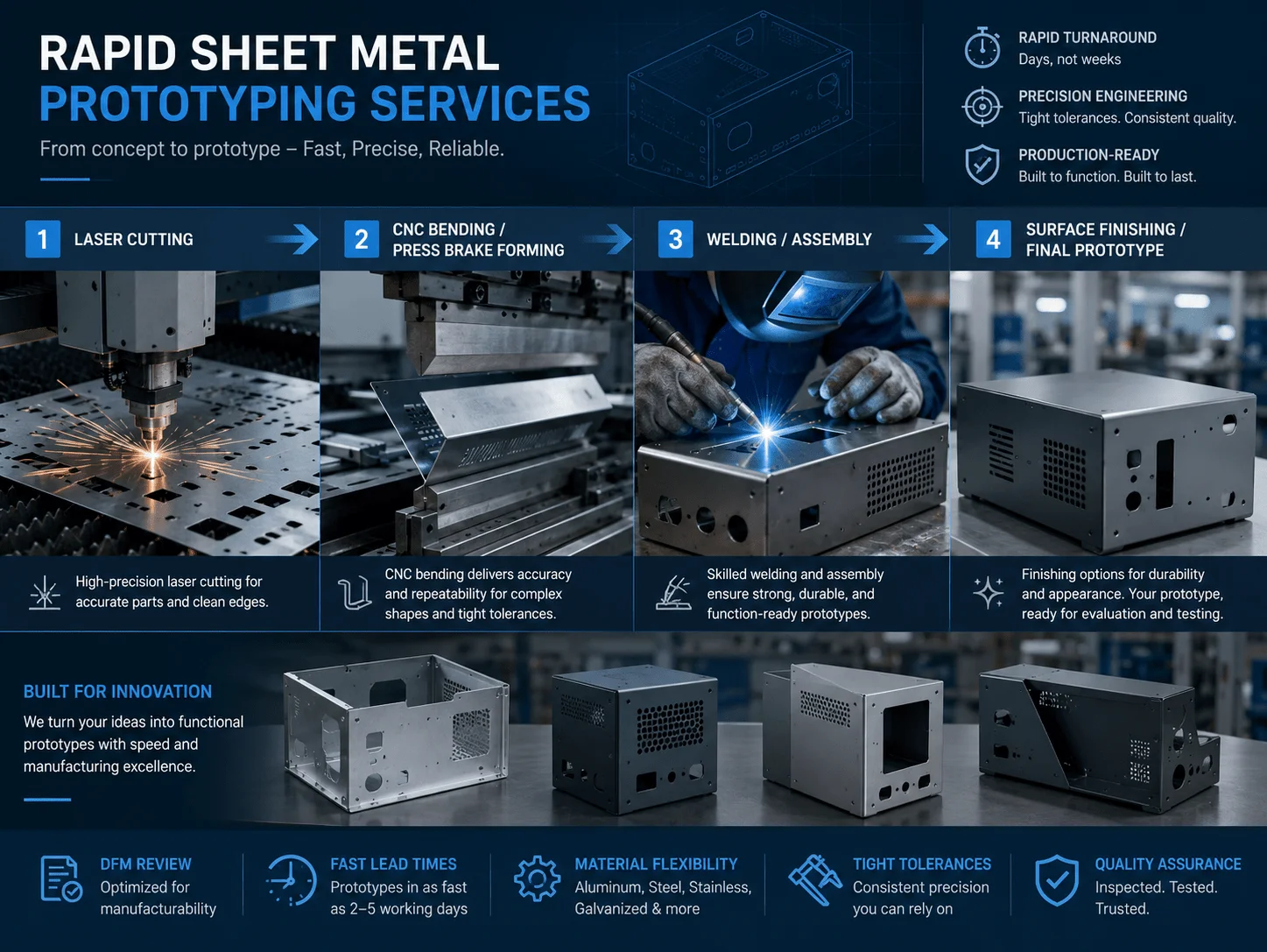
Sheet metal prototyping gives engineering teams a fast, production-relevant way to validate custom enclosures, brackets, panels, frames, covers, and structural components before committing to full-scale manufacturing. From corrosion-resistant medical equipment housings to lightweight aerospace assemblies and visually refined consumer electronics, sheet metal supports products that must combine strength, dimensional accuracy, manufacturability, and cost control.
For design engineers, NPI managers, procurement professionals, and product development teams, choosing the right material and fabrication process is only the beginning. Bend radii, hole locations, tolerance strategy, welding access, surface finishing, assembly requirements, and expected production quantity all affect the final result.
This guide explains how to design, source, and manufacture sheet metal prototypes efficiently. It covers industry applications, practical DFM rules, custom enclosure sourcing, low-volume cost analysis, supplier evaluation, and strategies for accelerating new product introduction.
How Sheet Metal Prototyping Works
Sheet metal fabrication converts flat metal stock into functional three-dimensional parts through a sequence of cutting, forming, joining, and finishing operations. A typical prototype may begin as a laser-cut blank, then move through bending, hardware installation, welding, grinding, surface treatment, inspection, and assembly.
Common fabrication processes include:
Fiber laser cutting
CNC punching
CNC press-brake bending
Rolling and forming
MIG, TIG, and spot welding
Riveting and mechanical fastening
PEM hardware installation
Grinding and deburring
Powder coating
Anodizing
Passivation
Brushing and polishing
Silk-screen printing
Laser marking
The most appropriate route depends on the material, sheet thickness, part size, geometric complexity, cosmetic standard, quantity, and final application.
| Process | Best Used For | Primary Advantage | Common Limitation |
| Laser cutting | Profiles, holes, vents, panels | Flexible and fast for prototypes | Heat-affected edges may require finishing |
| CNC punching | Repeated holes and standard forms | Efficient for repeat features | Tooling limits feature flexibility |
| Press-brake bending | Brackets, covers, chassis | Fast conversion from flat to formed part | Bend access and tooling clearance are required |
| Welding | Permanent assemblies and frames | Strong structural joints | Heat can cause distortion |
| Riveting and inserts | Serviceable assemblies | Fast assembly and replaceable hardware | Adds components and assembly steps |
| Powder coating | Durable colored finishes | Good corrosion and wear resistance | Coating thickness affects fit |
| Anodizing | Aluminum parts | Durable, premium metallic finish | Color consistency depends on alloy and batch |
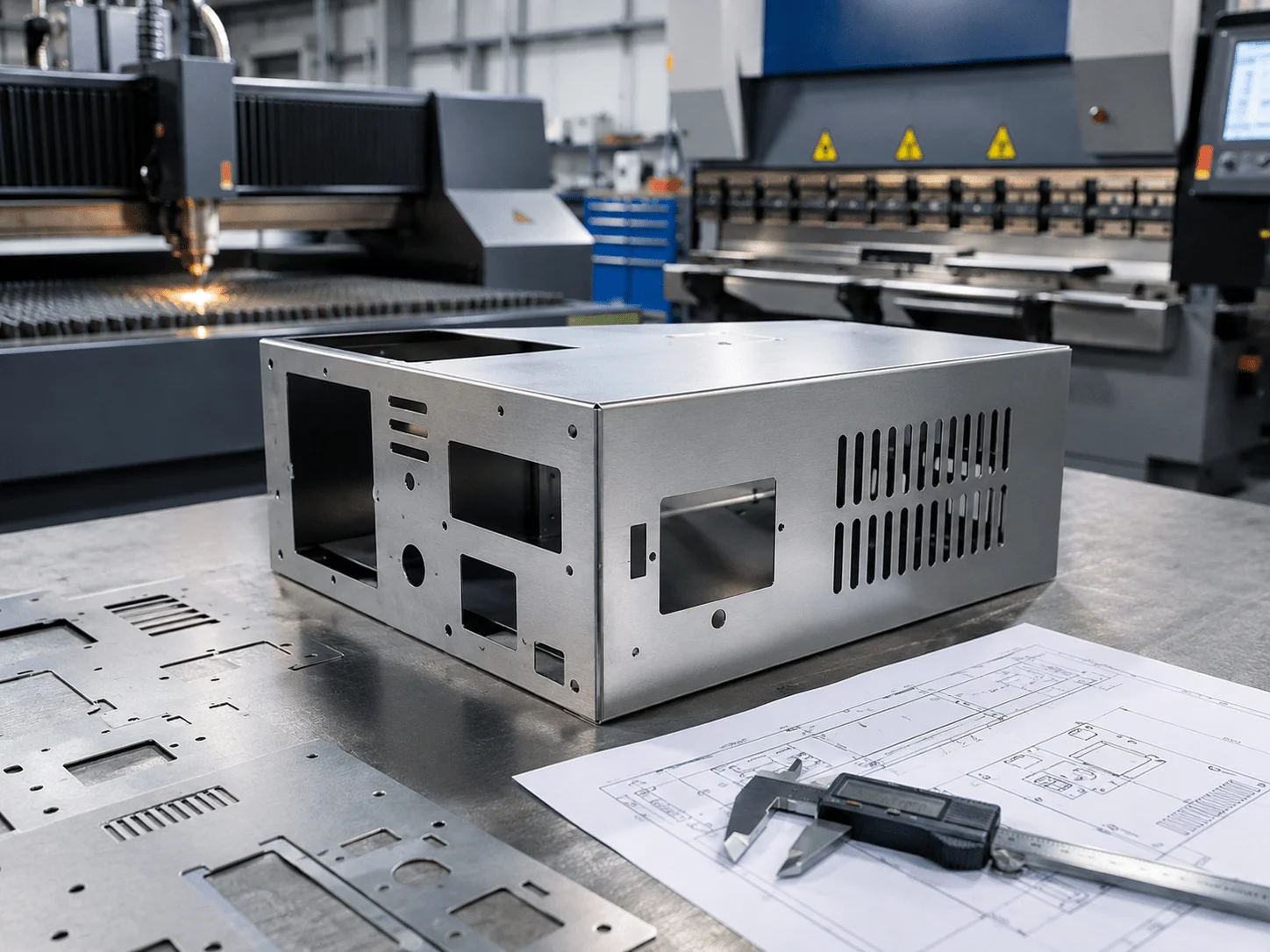
Industry Applications: Engineering the Future
Sheet metal is used across industries because it offers a strong combination of durability, relatively low material waste, short prototype lead times, and scalability. The same fundamental processes used for one prototype can often support pilot production and future repeat orders.
The details, however, vary greatly by industry. A medical equipment enclosure may prioritize corrosion resistance and cleanability. An aerospace bracket may prioritize weight, repeatable geometry, and documented inspection. A consumer electronics housing may need electromagnetic shielding, precise connector alignment, and a premium finish.
High-Quality sheet metal fabrication medical equipment
High-quality sheet metal fabrication medical equipment requires more than cutting and bending a stainless steel panel. Medical devices, laboratory instruments, diagnostic platforms, carts, cabinets, and equipment housings often operate in environments where cleanability, corrosion resistance, structural stability, and user safety are critical.
Stainless steel 304 and 316L are frequently considered for medical and laboratory applications. Stainless steel 316L offers strong corrosion resistance and is often selected when equipment may be exposed to cleaning chemicals, humidity, or demanding clinical environments. Aluminum can also be suitable for portable equipment, internal frames, panels, and lightweight diagnostic devices.
Typical sheet metal medical applications include:
Diagnostic equipment housings
Laboratory instrument covers
Medical carts and mobile workstations
Control panels
Monitor mounts
Imaging system enclosures
Instrument trays
Internal support frames
Ventilated electronics cabinets
Wall-mounted medical equipment
Design teams should pay particular attention to seams, exposed edges, recessed areas, fasteners, and weld quality. Difficult-to-clean gaps can collect contaminants, while sharp edges create safety concerns. Welds may need to be ground smooth, corners may require continuous joining, and exposed surfaces may need brushing, passivation, polishing, or powder coating.
The intended cleaning procedure should be discussed before material and finishing decisions are finalized. A coating that looks excellent during a design review may not perform well after repeated exposure to disinfectants. Similarly, a brushed stainless surface may be more appropriate than a painted finish in some environments.
Medical equipment development also benefits from early assembly testing. Prototype enclosures allow teams to validate cable routing, fan placement, access panels, wheel and handle mounting, serviceability, display angles, and internal equipment clearances before committing to production.
For B2B medical projects, a supplier should understand that quality is not limited to external appearance. Material traceability, dimensional reports, hardware verification, weld consistency, and documented finishing requirements may all be relevant to the project.
Meeting Rigid aerospace sheet metal fabrication tolerances
Meeting rigid aerospace sheet metal fabrication tolerances requires careful control of flat patterns, bend allowance, springback, hole position, fixture strategy, and inspection. Aerospace and defense components often combine lightweight materials with demanding fit requirements and low tolerance for production variation.
Common applications include:
Avionics enclosures
Equipment trays
Lightweight brackets
Internal aircraft panels
Sensor mounts
Structural covers
Electronic shielding components
UAV housings
Ground-support equipment
Communication system assemblies
Aluminum alloys are widely used where low weight is important. Stainless steel, titanium, and specialty alloys may be selected for higher temperature, strength, corrosion, or environmental requirements.
Tolerance must be defined feature by feature. Applying extremely tight tolerances to an entire sheet metal part can make production unnecessarily expensive and may not reflect how formed metal behaves. A more effective approach is to identify critical interfaces, datum features, mounting holes, mating surfaces, and assembly dimensions.
For example, the overall length of a cover may allow a wider tolerance, while mounting-hole position relative to a datum may need tighter control. Flatness after welding may require a dedicated fixture, while a non-critical cosmetic flange may not.
Bending introduces natural variation because material properties, grain direction, thickness, bend radius, and tool setup influence springback. Aerospace prototype suppliers therefore need a reliable method for bend compensation and first-article verification.
Inspection may include:
Caliper and micrometer checks
Height-gauge inspection
Coordinate measuring machine inspection
Optical measurement
Go/no-go fixtures
Flatness verification
Hole-pattern measurement
First-article inspection reports
Designers should avoid assuming that every laser-cut feature will maintain the same tolerance after bending and welding. Final geometry is affected by the complete manufacturing sequence, not only the cutting operation.
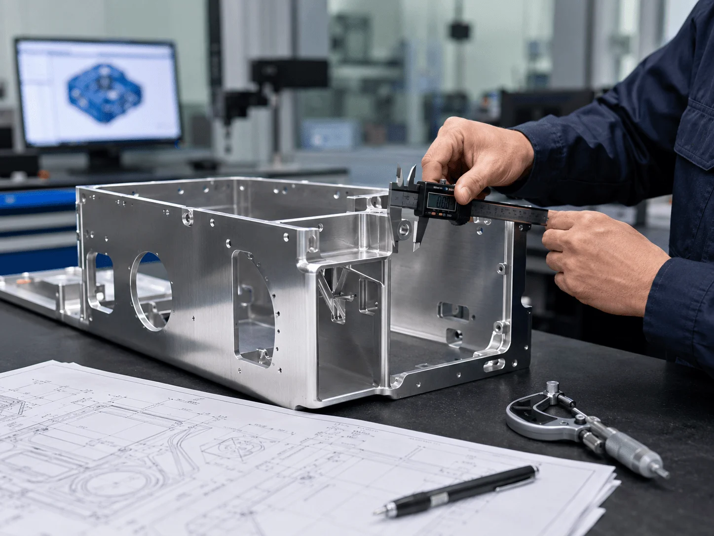
precision sheet metal parts for consumer electronics and Smart Hardware
Precision sheet metal parts for consumer electronics must balance technical performance with appearance. Smart devices, communication hardware, robotics controllers, battery systems, test equipment, and industrial electronics often rely on metal enclosures to protect internal components, manage heat, support connectors, and provide electromagnetic shielding.
Common applications include:
Smart-home control boxes
Communication equipment chassis
Battery enclosures
Camera housings
Robotics control cabinets
Network device panels
Power supply covers
Audio equipment chassis
Test instrument enclosures
Wearable-device production fixtures
Hardware engineers must coordinate the enclosure with printed circuit boards, displays, buttons, antennas, sensors, fans, connectors, and internal brackets. Even a small mismatch in hole location can prevent a connector from seating correctly or create excessive stress on a circuit board.
Electromagnetic interference shielding may influence material selection and assembly design. Conductive contact between panels can be affected by paint, anodizing, gaskets, plating, and fastener spacing. Teams should identify grounding and shielding requirements before selecting a cosmetic finish.
Thermal management is another major concern. Sheet metal allows engineers to incorporate:
Ventilation slots
Fan openings
Perforated regions
Heat-sink mounting points
Conductive internal structures
Louvers
Airflow channels
Exterior appearance is equally important for customer-facing products. Aluminum can be bead blasted and anodized for a clean metallic appearance. Steel can be powder coated in custom colors. Stainless steel can be brushed or polished. Logos, labels, port names, and safety information can be added through silk-screen printing or laser marking.
A high-quality consumer electronics prototype should allow the design and engineering teams to evaluate both function and perception. The enclosure should fit internal components, assemble correctly, feel rigid, align around ports, and present the intended visual identity.
Design for Manufacturability
Many sheet metal problems begin before the supplier receives the drawing. A design may function perfectly in CAD but be difficult to bend, weld, fixture, finish, or inspect.
Design for manufacturability reduces these risks by aligning the part geometry with practical fabrication methods. Effective DFM can shorten lead time, improve repeatability, and lower unit cost without changing the product’s intended function.
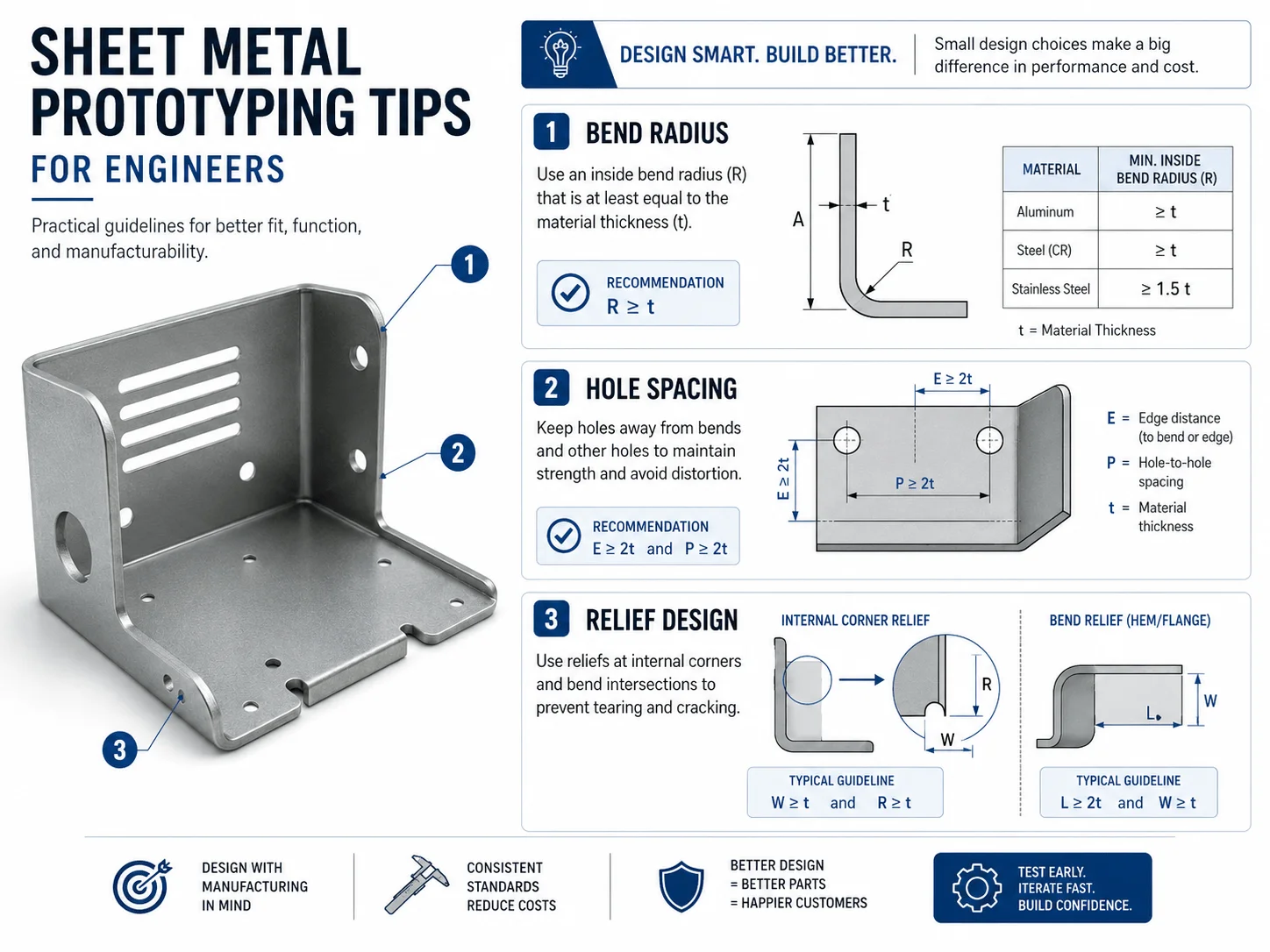
Crucial sheet metal prototyping tips for engineers
These practical sheet metal prototyping tips for engineers address the issues most frequently found during prototype review.
Maintain consistent material thickness
Most individual sheet metal parts should use a consistent thickness. Local thickness changes usually require separate components, machining, forming, or joining operations.
Using one standard gauge simplifies purchasing, bending, programming, and inspection. It also makes future production easier to scale.
Use a realistic minimum bend radius
A bend radius that is too small can cause cracking, distortion, or excessive thinning. The appropriate radius depends on the material, temper, thickness, grain direction, and forming method.
A radius near the material thickness is often a practical starting point for many common materials, but the supplier should confirm the final value.
Keep holes away from bend lines
Holes, slots, and cutouts placed too close to a bend may stretch or deform during forming. Move critical features away from bend zones or create relief features where necessary.
The required distance depends on hole size, material thickness, bend radius, and tooling.
Add bend relief where flanges meet
Bend reliefs can prevent tearing and unwanted deformation at corners. They also make it easier to form intersecting flanges cleanly.
Relief geometry should be simple and large enough for the material and process.
Avoid unnecessary tiny features
Very small holes, narrow bridges, and thin tabs can increase cutting time and distortion risk. They may also become damaged during deburring, bending, or finishing.
Only include miniature features when they serve a clear functional purpose.
Design for tooling access
Press-brake tooling needs physical space to form the part. Deep boxes, return flanges, and closely spaced bends can create tool interference.
A supplier may recommend staged bending, special tooling, removable panels, or a revised assembly structure.
Account for coating thickness
Powder coating, plating, and other finishes add material to surfaces. This can affect slots, press fits, threaded holes, grounding areas, hinge interfaces, and panel gaps.
Critical masked areas should be clearly marked on the drawing.
Select fastening methods early
PEM nuts, studs, rivet nuts, welded nuts, screws, rivets, and tabs each affect geometry and assembly. Hardware type, installation side, thread specification, and required clearance should be included in the technical package.
Avoid unnecessary cosmetic requirements
A highly cosmetic finish on every surface increases grinding, handling, masking, and inspection time. Identify visible Class-A surfaces and allow more practical standards on hidden areas.
Establishing a sheet metal dfm review checklist
A structured sheet metal dfm review checklist helps NPI engineers, manufacturing managers, and product teams identify problems before fabrication begins. This is more reliable than depending on informal drawing reviews.
The checklist should cover geometry, materials, tolerances, hardware, joining, finishing, inspection, and assembly.
Geometry and bending
Is material thickness clearly specified?
Are bend radii achievable?
Are holes far enough from bend lines?
Are bend reliefs included where needed?
Can standard press-brake tools access every bend?
Are return flanges likely to interfere with tooling?
Has springback been considered?
Is grain direction important?
Cutting and feature design
Are holes and slots suitable for laser cutting?
Are thin webs strong enough for handling?
Are corner radii practical?
Are ventilation features structurally stable?
Are cut edges exposed or hidden?
Is secondary machining required?
Welding and joining
Can the welder access every joint?
Is a welding fixture needed?
Could weld heat distort the assembly?
Are weld sizes and locations clearly defined?
Can mechanical fastening replace unnecessary welding?
Are removable service panels needed?
Hardware and assembly
Are PEM parts identified by manufacturer and part number?
Is hardware installation direction clear?
Are thread sizes and depths specified?
Is there enough tool access for final assembly?
Are cable and connector clearances verified?
Is tolerance stack-up acceptable?
Surface finishing
Is the finish compatible with the material?
Are cosmetic surfaces identified?
Are masked areas shown?
Will coating thickness affect assembly?
Is color or texture specified using a recognized standard?
Are grounding areas protected from paint?
Inspection and documentation
Are critical dimensions identified?
Are datums clearly defined?
Are general tolerances realistic?
Is a first-article report required?
Are material certificates required?
Are cosmetic acceptance standards documented?
The best DFM review is collaborative. The manufacturer should explain why a feature is difficult and propose a practical alternative. The engineering team should explain the function so the supplier does not modify something critical.
Sheet Metal Materials and Finishes
Material selection affects weight, corrosion resistance, strength, appearance, weldability, conductivity, and price.
| Material | Key Advantages | Common Applications |
| Aluminum 5052 | Formable, lightweight, corrosion resistant | Enclosures, panels, brackets |
| Aluminum 6061 | Strong and machinable | Frames, thicker plates, structural parts |
| Stainless steel 304 | Corrosion resistant and durable | Food, medical, laboratory equipment |
| Stainless steel 316L | Strong corrosion resistance | Medical, marine, chemical environments |
| Cold-rolled steel | Cost-effective and strong | Cabinets, brackets, industrial housings |
| Galvanized steel | Protective zinc coating | Outdoor and industrial enclosures |
| Copper | Conductive and formable | Electrical and thermal applications |
| Brass | Conductive and decorative | Electrical parts and premium components |
Material selection should consider the full manufacturing sequence. Aluminum 6061 is strong but is generally less formable than 5052 for tight bends. Stainless steel is durable but requires more forming force. Cold-rolled steel is economical but usually needs coating to improve corrosion resistance.
Finishing options include:
As-fabricated
Deburred
Brushed
Polished
Bead blasted
Powder coated
Wet painted
Anodized
Passivated
Zinc plated
Nickel plated
Silk-screen printed
Laser marked
Sourcing and Cost Optimization
A successful sourcing strategy considers more than the lowest quotation. Prototype quality, technical communication, revision control, surface finishing, inspection, packaging, and repeat-order capability all influence total project cost.
Sourcing custom sheet metal prototype enclosures Efficiently
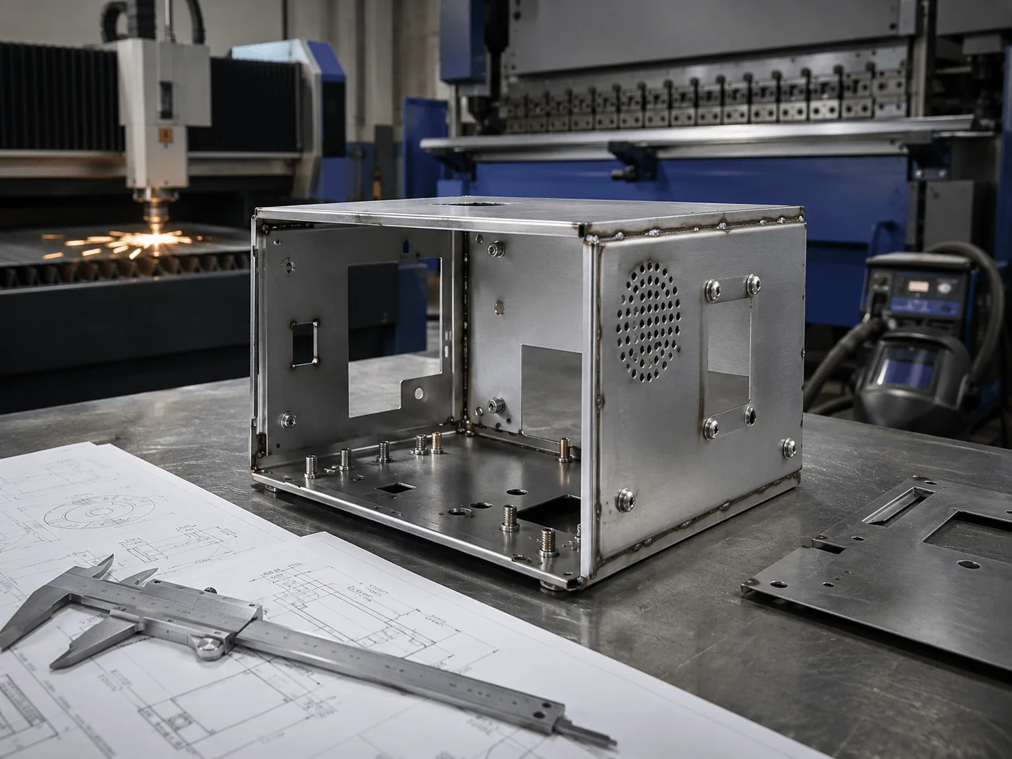
Sourcing custom sheet metal prototype enclosures efficiently begins with a complete RFQ package. At the prototype stage, suppliers often lose time clarifying missing material specifications, undefined finishes, incomplete drawings, or inconsistent CAD models.
A useful quotation package should include:
STEP or native 3D CAD files
Flat pattern when available
Fully dimensioned 2D PDF drawings
Material type and thickness
Required quantity
Surface finish
Color and texture
Hardware list
Welding requirements
Critical tolerances
Cosmetic surface classification
Inspection requirements
Desired delivery date
For one to ten enclosures, the primary objective is usually design validation. Teams need to check structural integrity, internal component fit, connector alignment, access, cooling, appearance, and assembly sequence.
The fastest supplier is not necessarily the one with the shortest cutting time. A supplier that can manage cutting, bending, hardware, welding, finishing, printing, inspection, and assembly under one workflow may reduce total lead time by avoiding transfers between multiple subcontractors.
When comparing quotations, review:
Included operations
Material grade
Hardware assumptions
Finish specification
Inspection scope
Packaging
Freight
Tooling or fixture charges
Revision policy
Lead time after approval
A low quotation that excludes hardware installation or finishing may become more expensive once all required processes are added.
Managing low volume sheet metal production cost
Managing low volume sheet metal production cost becomes critical when a project moves from several prototypes into an NPI batch of 10–200 parts. At this stage, the team needs production consistency but may not be ready for dedicated high-volume tooling.
Sheet metal works well for low-volume production because laser cutting and CNC bending require relatively little dedicated tooling. However, manual setup, welding, finishing, and inspection can still create substantial cost.
Main cost drivers
Material
Large parts, thick sheets, premium alloys, and inefficient nesting increase raw-material cost. Designing parts around standard sheet sizes and common thicknesses can reduce waste.
Cutting time
Long cutting paths, dense perforations, many small holes, and intricate decorative patterns increase machine time. Simplifying non-critical features can reduce cost.
Bending operations
Each bend requires setup, handling, and machine time. Complex bend sequences or special tooling increase labor. Combining compatible bends and avoiding unnecessary flanges can improve efficiency.
Welding
Welding is frequently one of the largest labor costs. Long seams, cosmetic grinding, fixture requirements, and distortion correction increase price.
Where appropriate, tabs, slots, screws, rivets, or PEM hardware may reduce welding.
Surface finishing
Powder coating is generally cost-effective for batches but may carry minimum lot charges. Custom colors, multi-color finishes, masking, polishing, and high cosmetic standards add cost.
Inspection
Standard dimensional checks are less expensive than complete inspection reports. Critical aerospace, medical, or regulated projects may require more documentation.
Prototype and low-volume cost comparison
| Quantity | Typical Manufacturing Strategy | Unit-Cost Behavior | Main Objective |
| 1–5 parts | Laser cutting, manual bending, minimal fixtures | Highest | Design and assembly validation |
| 6–20 parts | Reusable setup and simple fixtures | Lower | Engineering and user testing |
| 21–100 parts | Batch processing and standardized inspection | Moderate | NPI and pilot production |
| 101–200 parts | Optimized nesting, fixtures, repeat workflows | Lower | Market launch and bridge production |
| 200+ parts | Evaluate dedicated tooling and automation | Project-dependent | Repeat production |
Practical cost-reduction methods
Use standard sheet thicknesses.
Reduce unnecessary material types within one assembly.
Combine similar parts into one production batch.
Simplify weld joints.
Use self-locating tabs and slots.
Standardize PEM hardware.
Avoid custom powder colors for very small batches.
Limit tight tolerances to critical dimensions.
Identify cosmetic surfaces rather than treating every face as cosmetic.
Design parts for efficient nesting.
Avoid repeated setup changes.
Approve one validated golden sample before the full batch.
A procurement team should also consider lifecycle cost. A slightly higher prototype price may be justified if the supplier identifies a design issue that prevents a costly production failure.
Application Scenario Comparison
| Industry | Typical Sheet Metal Parts | Primary Engineering Priorities | Common Materials |
| Medical equipment | Carts, diagnostic housings, panels | Cleanability, corrosion resistance, safety | 304, 316L, aluminum |
| Aerospace and defense | Brackets, avionics boxes, trays | Weight, tolerance, documentation | Aluminum, stainless steel, titanium |
| Consumer electronics | Chassis, covers, internal shields | Appearance, EMI, connector alignment | Aluminum, steel, copper |
| Automotive and transportation | Battery boxes, brackets, covers | Strength, vibration, corrosion resistance | Steel, aluminum |
| Robotics and automation | Control cabinets, frames, guards | Rigidity, serviceability, low volume | Steel, aluminum, stainless steel |
| Industrial equipment | Enclosures, panels, machine guards | Durability, cost, repeatability | Cold-rolled and galvanized steel |
Speeding Up Your NPI Timeline
New product introduction involves many dependent activities: mechanical design, electronics, firmware, testing, certification, sourcing, packaging, and production planning. Delays in one enclosure can block several other teams.
The right supplier helps maintain schedule by reviewing designs quickly, identifying fabrication risks before production, consolidating processes, and communicating revision status clearly.
Choosing the Right rapid sheet metal prototyping services
Choosing the right rapid sheet metal prototyping services requires evaluating technical capability, not only advertised lead time. A supplier should be able to move from CAD review to cutting, forming, joining, finishing, inspection, and delivery without losing control of revisions.
Key capabilities include:
Rapid DFM feedback
Fiber laser cutting
CNC bending
Hardware installation
TIG and spot welding
Grinding and deburring
Powder coating and anodizing
Silk-screen printing
Dimensional inspection
Small-batch assembly
Secure packaging
International delivery support
A reliable rapid supplier should also ask good questions. For example:
Which dimensions are critical?
Which surfaces are cosmetic?
Does the enclosure require electrical grounding?
Will coating affect the fit?
Is the prototype intended for testing or presentation?
Is the design likely to change?
What quantity may follow after approval?
These questions indicate that the supplier is considering the product’s function rather than simply fabricating the geometry.
A practical NPI workflow
1.Submit 3D CAD files, 2D drawings, material, finish, and quantity.
2.Complete a technical DFM review.
3.Resolve bending, welding, tolerance, and finishing risks.
4.Produce the first prototype.
5.Inspect critical dimensions.
6.Complete engineering assembly and functional testing.
7.Revise the design if necessary.
8.Approve a golden sample.
9.Launch the pilot-production batch.
10.Establish repeatable quality and packaging standards.
This approach helps teams separate design validation from production approval. It also reduces the risk of ordering a large batch before the enclosure has been fully tested.
Frequently Asked Questions
What is sheet metal prototyping?
Sheet metal prototyping is the process of manufacturing a small number of metal panels, enclosures, brackets, frames, or assemblies for design validation. It commonly uses laser cutting, CNC bending, hardware installation, welding, and finishing.
What information is needed for a sheet metal quote?
Provide a 3D CAD model, 2D drawing, material and thickness, quantity, finish, hardware specifications, welding requirements, critical tolerances, cosmetic requirements, and expected delivery date.
What is the best material for a sheet metal enclosure?
The best material depends on the application. Aluminum is lightweight and corrosion resistant. Cold-rolled steel is strong and economical. Stainless steel is durable and suitable for corrosion-sensitive environments.
What are the most important sheet metal DFM rules?
Use practical bend radii, keep holes away from bend lines, include bend reliefs, maintain consistent thickness, account for coating, provide tooling access, and avoid unnecessary tight tolerances.
How accurate is sheet metal fabrication?
Accuracy depends on material, thickness, cutting process, bending, welding, part size, and geometry. Critical tolerances should be discussed with the supplier and defined relative to clear datums.
How can welding distortion be reduced?
Welding distortion can be reduced through balanced weld sequencing, shorter welds, mechanical fastening, appropriate fixtures, controlled heat input, and designs that do not concentrate welds in one area.
Is sheet metal cost-effective for 10–200 parts?
Yes. Sheet metal is often highly suitable for low-volume production because laser cutting and CNC bending require limited dedicated tooling. Unit cost generally decreases as setup and finishing costs are spread across the batch.
Can sheet metal prototypes include a final cosmetic finish?
Yes. Prototypes can be powder coated, anodized, brushed, polished, plated, painted, silk-screen printed, or laser marked. Cosmetic standards should be agreed before manufacturing.
What is the difference between a prototype enclosure and a production enclosure?
A prototype enclosure validates geometry, assembly, function, and appearance. A production enclosure should also use repeatable processes, approved inspection standards, controlled finishes, documented revisions, and stable packaging.
How quickly can a sheet metal prototype be produced?
Lead time depends on complexity, material availability, welding, hardware, finishing, inspection, and quantity. Simple unfinished parts can be faster than welded, powder-coated, or highly cosmetic assemblies.
Sheet metal prototyping creates a practical bridge between CAD design and production-ready hardware. It allows engineering teams to validate structure, assembly, thermal management, connector placement, safety, appearance, and serviceability using processes that closely reflect future manufacturing.
Successful projects begin with industry-appropriate materials and realistic tolerance strategies. They continue with disciplined DFM, complete technical documentation, efficient sourcing, and a supplier capable of supporting both prototypes and low-volume production.
Medical equipment teams may prioritize corrosion resistance and cleanability. Aerospace programs may focus on weight, inspection, and controlled tolerances. Consumer electronics developers may need EMI performance and premium aesthetics. Procurement and NPI teams must balance all of these requirements against lead time and total project cost.
Accelerate Your Sheet Metal Project with GC-Prototype
Accelerating your NPI timeline requires a reliable manufacturing partner who understands your industry standards. Whether you are a Senior Mechanical Engineer developing medical carts or a Sourcing Manager looking for electronics enclosures, GC-Prototype delivers.
Our capabilities include custom sheet metal fabrication, laser cutting, CNC bending, hardware installation, welding, powder coating, anodizing, silk-screen printing, prototype assembly, and low-volume production.