Address:
Shenzhen Bao'an District Xinqiao Subdistrict Huangpu Community Huangpu East Ring Road No. 504 Shenzhen Yuan Industrial City Building C
Work Hours:
Monday to Friday: 9AM - 21PM
Weekend: 9AM - 21PM

Address:
Shenzhen Bao'an District Xinqiao Subdistrict Huangpu Community Huangpu East Ring Road No. 504 Shenzhen Yuan Industrial City Building C
Work Hours:
Monday to Friday: 9AM - 21PM
Weekend: 9AM - 21PM

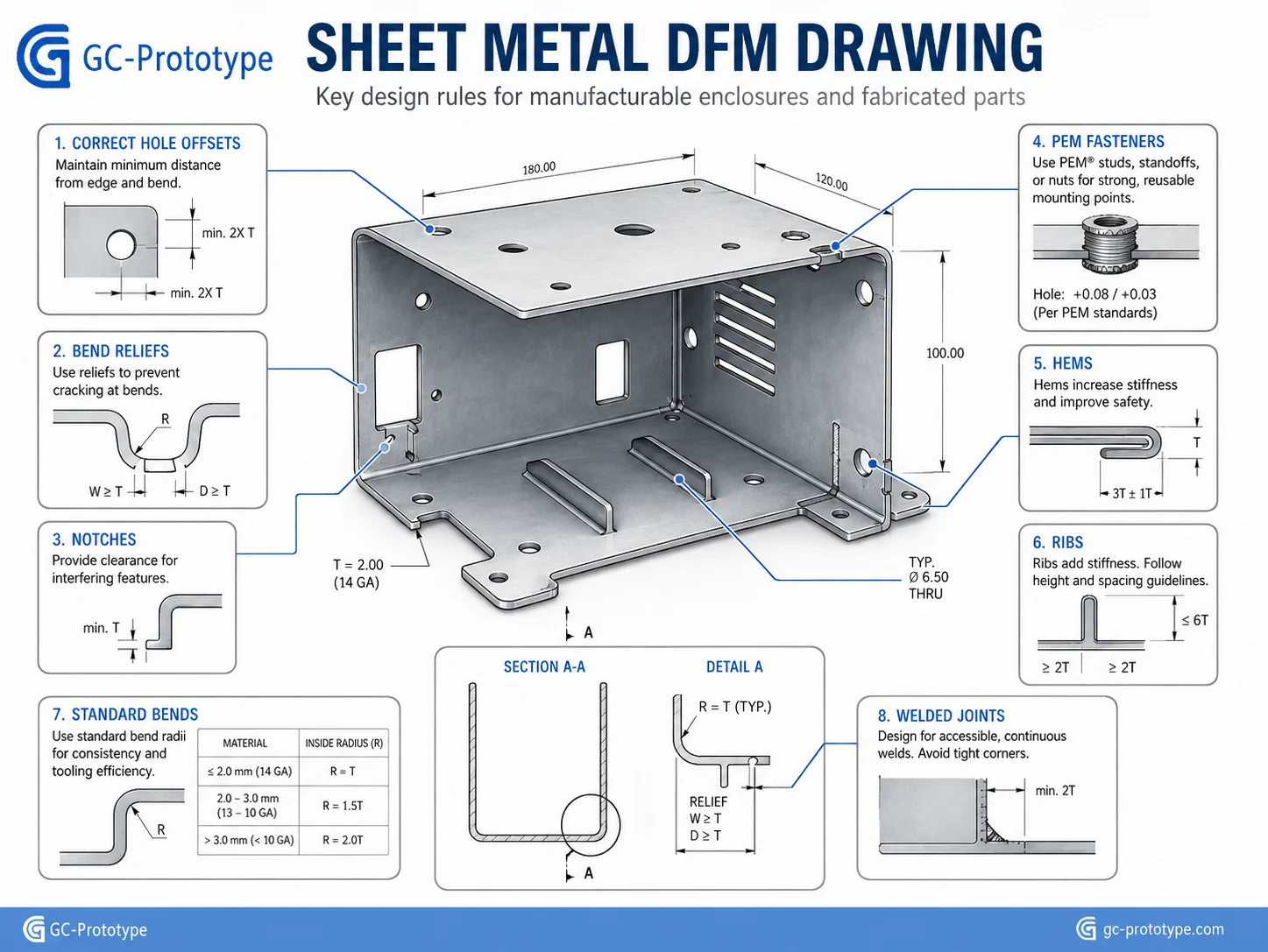
Sheet metal fabrication is one of the most practical manufacturing routes for producing structural enclosures, equipment cabinets, brackets, chassis, panels, and machine guards. It combines high strength, low weight, fast lead times, and scalable production without requiring the heavy tooling investment associated with molded or cast parts. For Senior Mechanical Engineers, Product Designers, NPI Managers, and Procurement Professionals, however, a successful sheet metal project depends on much more than selecting a material and sending a flat pattern to a supplier.
Bend allowances, grain direction, minimum radii, hole-to-bend distance, weld access, hardware selection, surface finishing, tolerance strategy, and production quantity all influence cost and quality. A design that looks simple in CAD can become expensive if it requires nonstandard material thicknesses, repeated setups, custom tooling, excessive welding, or tight tolerances across flexible panels.
This guide explains industry applications, medical-enclosure requirements, industrial automation structures, bending calculations, laser cutting and stamping economics, practical DFM rules, material selection, quality control, and supplier qualification for Western B2B manufacturing programs.
How Sheet Metal Fabrication Works
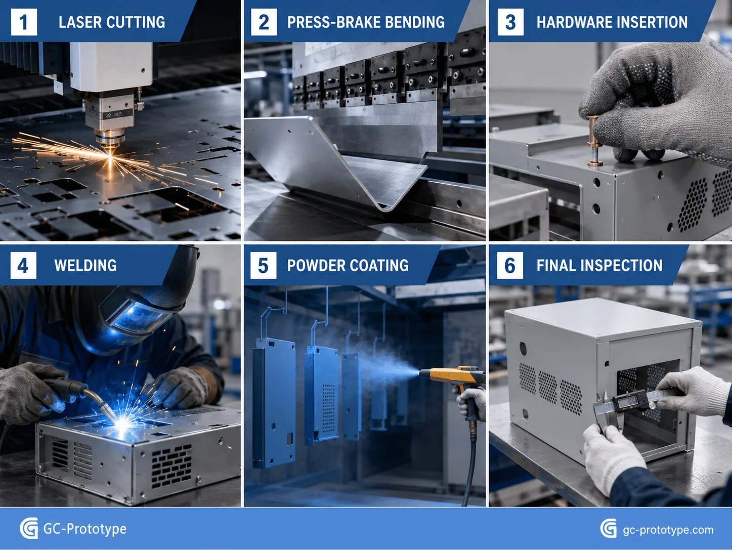
Sheet metal fabrication converts flat metal stock into functional three-dimensional parts through cutting, forming, joining, and finishing. A typical workflow begins with a 3D model and dimensioned drawing. The manufacturing engineer unfolds the geometry into a flat pattern, applies bend allowances, nests parts on standard sheets, and selects the appropriate fabrication route.
Laser cutting is widely used for prototypes and low-volume parts because it can create complex profiles without dedicated cutting dies. CNC punching is effective when a design contains repeated holes, louvers, knockouts, or standard formed features. Press brakes create bends using matched punches and dies, while welding, riveting, clinching, and self-clinching hardware complete the assembly.
A typical production sequence includes:
1.Design and DFM review
2.Flat-pattern development
3.Material procurement and incoming inspection
4.Laser cutting or CNC punching
5.Deburring and edge preparation
6.Press-brake forming
7.Hardware insertion
8.Welding or mechanical assembly
9.Grinding and cosmetic preparation
10.Powder coating, plating, passivation, or anodizing
11.Dimensional and visual inspection
12.Packaging and delivery
The process can support one-off prototypes, pilot batches, and thousands of production units. The optimal route changes with volume. A laser-cut and press-brake-formed enclosure may be economical at 20 units, while a high-volume program may justify progressive stamping dies, robotic welding, dedicated fixtures, and automated inspection.
| Fabrication Method | Upfront Tooling | Production Flexibility | Best Quantity Range | Main Advantage |
| Laser cutting and bending | Low | Very high | 1–500+ | Fast changes and no hard cutting tool |
| CNC punching and bending | Low to moderate | High | 50–2,000+ | Efficient repeated holes and standard forms |
| Soft tooling and forming | Moderate | Medium | Hundreds to several thousand | Faster forming for stable designs |
| Progressive stamping | High | Low after tool release | 10,000+ | Very low unit cost at scale |
Industry Applications & Design Standards
Healthcare Engineering: Following sheet metal design guidelines for medical enclosures
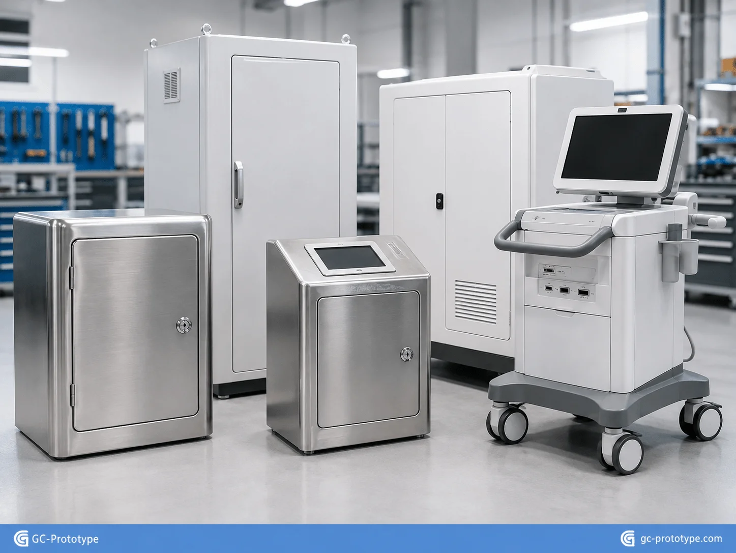
Following sheet metal design guidelines for medical enclosures requires designers to balance structural rigidity, cleanability, corrosion resistance, sealing, service access, appearance, and regulatory documentation. Diagnostic systems, laboratory equipment, mobile carts, imaging devices, sterilization equipment, and medical control cabinets often use fabricated metal structures because they can carry heavy internal components while remaining serviceable and relatively lightweight.
Material selection begins with the operating environment. Powder-coated cold-rolled steel provides good stiffness and economical fabrication for general indoor equipment. Stainless steel 304 offers corrosion resistance and cleanability for many clinical and laboratory environments. Stainless steel 316L may be selected when stronger resistance to chlorides or aggressive cleaning chemicals is required. Aluminum reduces weight and can support anodized or powder-coated finishes, but joint design, grounding, and surface durability need careful review.
Cleanability should be designed into the geometry. External surfaces benefit from smooth transitions, closed seams, accessible corners, and controlled gaps. Deep crevices, exposed unfinished edges, and overlapping joints can trap moisture or cleaning residue. Weld beads on visible or hygienic surfaces may need continuous welding and controlled grinding rather than intermittent tack welding.
Sealing requirements should be translated into specific design controls. An IP target affects door overlaps, gasket compression, fastener spacing, cable entries, ventilation, and weld continuity. A gasket cannot compensate for an enclosure flange that distorts during welding or powder coating. The flange should have sufficient stiffness, consistent contact width, and a verified compression path.
Medical appearance requirements also influence manufacturing. Large flat panels can reveal waviness, weld distortion, grinding marks, and powder-coat variation. Strategic returns, hems, beads, ribs, and internal supports increase stiffness without using excessively thick sheet. Cosmetic surfaces should be identified on the drawing, together with acceptable weld visibility, grain direction, gloss, color, and masking requirements.
To prevent seam cracking and distortion, the design team should avoid placing heavy welds at unsupported corners. Tabs, slots, locating features, and dedicated fixtures can stabilize assembly. Heat input should be minimized and distributed, especially on stainless steel and thin panels. Where hygiene allows, clinching, riveting, or self-clinching hardware may reduce welding and finishing labor.
Designing Mobile Medical Carts and Equipment Frames
Mobile medical carts combine sheet metal panels with tubing, machined components, casters, drawers, and electrical hardware. The structure must withstand static loads, repeated movement, impact, and cleaning while maintaining stability.
Engineers should define the center of gravity, caster spacing, shelf loading, handle forces, cable routing, and service access before finalizing the enclosure. Internal components should mount to reinforced rails or formed channels rather than relying on broad unsupported panels. Fasteners used for maintenance should be accessible without removing unrelated assemblies.
Industrial Automation: Sourcing custom sheet metal fabrication for industrial automation
Sourcing custom sheet metal fabrication for industrial automation requires close attention to structural loading, mounting accuracy, vibration, electrical safety, ventilation, and field serviceability. Typical parts include control cabinets, robotic bases, machine guards, sensor brackets, conveyor covers, electrical panels, battery enclosures, and welded support frames.
Automation equipment is often customized around a production line, which makes low-to-medium-volume fabrication particularly valuable. Laser cutting and press-brake forming allow rapid design changes without rebuilding expensive hard tooling. A supplier can produce engineering prototypes, installation kits, and repeat batches from the same digital data.
Rigidity is a common challenge. Simply increasing sheet thickness adds weight and material cost. Formed returns, flanges, hat sections, embossments, louvers, beads, and ribs can increase stiffness more efficiently. A broad flat panel that vibrates during machine operation may become stable after adding a shallow formed feature or reinforced perimeter.
Mounting holes should be referenced to functional datums rather than to multiple formed edges that accumulate tolerance. Critical interfaces for motors, rails, gearboxes, and sensors may need machined plates, welded inserts, or post-weld machining. Oversized clearance holes and slotted adjustments can help accommodate installation variation where precision location is not functionally necessary.
Control cabinets also need a clear thermal strategy. Fans, filters, heat exchangers, and vents should be positioned around the actual heat load. Louvers and perforations affect enclosure strength and sealing, while internal cable paths must remain separated from moving mechanisms and high-temperature components.
Designers should consider service conditions at the factory floor. Doors need adequate hinge support and opening clearance. Removable panels should use captive fasteners where practical. Labels, grounding studs, DIN rails, gland plates, and cable-entry zones should be included in the manufacturing drawing and bill of materials.
Engineering Precision & Cost Trade-Offs
Precision Bending: Utilizing the sheet metal bending radius standard chart
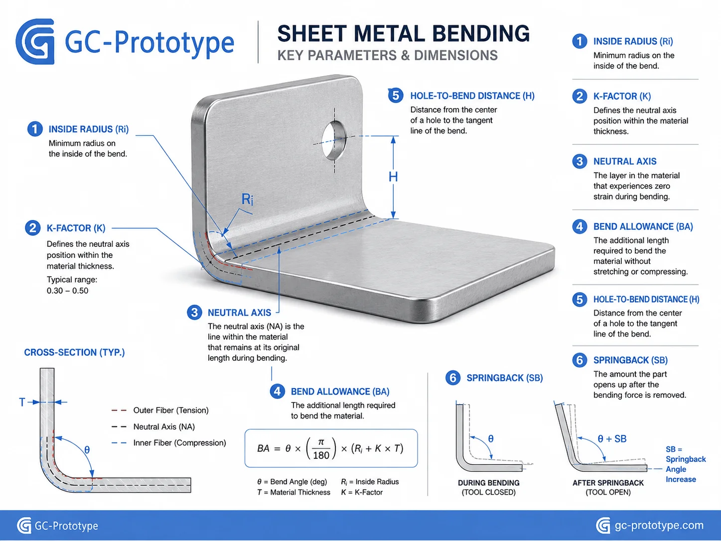
Using a sheet metal bending radius standard chart helps Mechanical and Process Engineers select practical internal radii, estimate bend deductions, and prevent cracking or dimensional errors. However, a chart should be treated as a starting reference rather than a universal guarantee because bend results vary with alloy, temper, thickness, grain direction, tooling, bend angle, and press-brake method.
During bending, the outer surface stretches while the inner surface compresses. Between them lies a neutral axis that experiences little change in length. The neutral axis does not remain at the exact center of the material; its position is commonly described by the K-factor.
The bend allowance can be estimated as:
Bend allowance = bend angle in radians × (inside radius + K-factor × material thickness)
The correct K-factor depends on the process and tooling. Air bending, bottoming, and coining produce different material behavior. Many initial calculations use a moderate K-factor range, but production flat patterns should be calibrated against the actual press brake, V-die opening, material batch, and supplier bend table.
An indicative minimum inside-radius guide is shown below:
| Material | Typical Starting Inside Radius | Design Consideration |
| Mild steel | About 1.0 × thickness | Confirm for high-strength grades |
| Stainless steel | About 1.0–1.5 × thickness | Greater springback and forming force |
| Aluminum 5052-H32 | About 1.0 × thickness | Commonly suitable for formed enclosures |
| Aluminum 6061-T6 | Often 2.0–3.0 × thickness | Higher cracking risk in tight bends |
| Copper or brass | Grade-dependent | Grain direction can be critical |
These values are general design guidance. The supplier’s verified tooling chart and the exact material specification should control the released design.
Hole placement is equally important. A hole positioned too close to a bend can stretch into an oval, tear, or pull toward the bend line. As a practical starting point, the edge of a hole should be separated from the bend by the inside radius plus a multiple of material thickness. Large holes and slots may require even more space.
Bend reliefs are useful where a bend terminates near an edge or adjacent flange. A relief prevents tearing and allows the material to form without uncontrolled distortion. The relief should be wide enough for the tool and extend beyond the bend line while avoiding sharp corners that may initiate cracks.
Managing Springback and Bend Sequence
Springback occurs when the material partially returns toward its original shape after forming pressure is released. Stainless steel, high-strength steel, and some aluminum alloys may show significant springback. The press-brake program compensates through overbending, tooling selection, and measured process data.
Bend sequence affects whether the part can physically fit between the punch, die, machine frame, and already-formed flanges. A CAD model may be geometrically valid yet impossible to bend without custom tooling. DFM should therefore include a bend-sequence review before the drawing is released.
Cost Breakdown: laser cutting vs stamping sheet metal cost
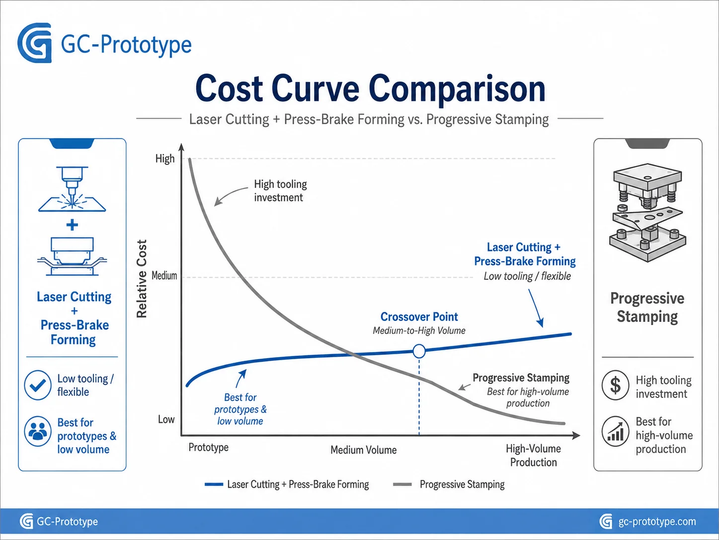
The laser cutting vs stamping sheet metal cost comparison depends primarily on quantity, geometry stability, material, part size, secondary forming, and expected program life.
Laser cutting has minimal dedicated tooling. The supplier programs the profile directly from CAD, making it ideal for NPI, prototypes, spare parts, customized products, and batches from one unit to several hundred or more. Engineering changes can be implemented quickly by updating the flat pattern.
Stamping uses a dedicated die to cut, pierce, form, or progressively shape the part. Tooling investment can be substantial, but the cycle time per part becomes very low once production begins. Progressive dies can perform several operations during each press stroke, making them suitable for stable designs with annual quantities in the tens or hundreds of thousands.
| Cost Factor | Laser Cutting and Bending | Hard-Tool Stamping |
| Initial tooling | Low | High |
| Engineering changes | Fast and inexpensive | May require tool modification |
| Unit cost at low volume | Usually lower | Tooling dominates |
| Unit cost at high volume | Higher | Usually much lower |
| Geometry flexibility | Very high | Limited after tool release |
| Lead time | Short | Longer tooling development |
| Best fit | NPI and 1–500+ parts | Stable production, often 10,000+ parts |
The break-even point cannot be determined by quantity alone. A simple washer-like part may justify stamping at a relatively modest volume, while a large enclosure with many bends and welds may continue to use laser cutting even at several thousand units.
Procurement teams should compare total cost of ownership, including die design, tool manufacture, sampling, maintenance, press setup, material utilization, scrap, deburring, forming, hardware insertion, finishing, inspection, packaging, and engineering-change risk.
A useful sourcing strategy is to request quotations for several volume levels. For example, a supplier might price 50, 250, 1,000, 5,000, and 20,000 units using alternative processes. This reveals where soft tooling, turret punching, dedicated fixtures, robotic welding, or hard stamping begins to offer value.
Essential DFM Rules for Cost Reduction
Practical DFM Rules: Hole Offsets, Notch Design, and Hardware Inserts
Practical sheet metal DFM reduces cutting time, press-brake setups, distortion, welding, rework, and inspection. The most valuable improvements are usually made before the first flat pattern is released.
Keep Holes Away from Bend Zones
Holes, slots, and cutouts located too close to a bend may elongate or distort. Increase the offset, add a relief, or create the feature after bending when its final position is critical.
Design Notches and Bend Reliefs Deliberately
A notch should not terminate in an uncontrolled sharp corner where stress can concentrate. Use practical relief geometry that extends beyond the bend region and is compatible with the cutting process.
Select Compatible Hardware Inserts
Self-clinching nuts, studs, standoffs, and threaded inserts reduce welding and tapping, but each fastener has minimum thickness, hardness, edge-distance, and installation requirements. The selected part number must match the sheet specification.
Hardware should be installed before coating when the process and grounding requirement allow, but masking and thread protection must be planned. Stainless fasteners in aluminum structures may also require corrosion and galvanic compatibility review.
Standardize Material Thickness
Nonstandard sheet thicknesses can increase minimum-order quantities, procurement lead time, and scrap. Standardizing thickness across a product family improves nesting, purchasing leverage, and inventory control.
Minimize Unnecessary Welding
Welding adds labor, heat distortion, grinding, inspection, and cosmetic risk. Tabs, slots, bends, hems, rivets, clinching, and mechanical fasteners may reduce weld length while improving assembly repeatability.
Use Hems, Returns, and Beads for Stiffness
A hem can remove a sharp edge and increase local stiffness. Formed returns and beads can strengthen large panels without thicker material. These features must be compatible with available tooling and bend sequence.
Design for Standard Press-Brake Tooling
Special offsets, closed channels, very short flanges, and deep boxes may require custom punches or staged forming. Using standard bend angles, radii, and accessible flange geometry reduces setup and tooling cost.
| DFM Risk | Likely Result | Preferred Response |
| Hole beside bend line | Elongation or tearing | Increase offset or add relief |
| Sharp notch at bend | Crack initiation | Use a rounded or extended relief |
| Insert incompatible with thickness | Rotation or pullout | Follow fastener specifications |
| Large unsupported panel | Oil-canning and vibration | Add returns, ribs, or beads |
| Excessive welding | Distortion and cosmetic rework | Use tabs, bends, or fasteners |
| Custom material thickness | Higher purchasing cost | Select a standard gauge |
Material Selection for Sheet Metal Parts
Material choice affects strength, weight, corrosion resistance, formability, weldability, finish, and price. The lowest raw-material cost may not produce the lowest finished-part cost if the alloy is difficult to bend, weld, or finish.
| Material | Main Advantages | Common Applications | Key Limitation |
| Cold-rolled steel | Economical, stiff, weldable | Cabinets, brackets, indoor equipment | Requires corrosion protection |
| Galvanized steel | Built-in corrosion resistance | HVAC, electrical, and industrial panels | Welding and cosmetics need planning |
| Stainless steel 304 | Corrosion resistance and cleanability | Medical, food, and laboratory equipment | Higher cost and springback |
| Stainless steel 316L | Stronger chemical resistance | Harsh medical and marine environments | Premium material cost |
| Aluminum 5052 | Lightweight and formable | Enclosures, electronics, transportation | Lower stiffness than steel |
| Aluminum 6061 | Strong and machinable | Frames, plates, and structural parts | T6 condition is less bend-friendly |
Surface finishing must be integrated into the design. Powder coating adds durable color and corrosion protection but requires grounding, masking, drainage, and racking points. Anodizing is common for aluminum, although welds and different alloy batches may show color variation. Stainless steel may be brushed, bead blasted, passivated, or electropolished depending on function and appearance.
Coating thickness can affect tight slots, hinges, electrical contacts, threaded holes, and mating interfaces. These areas should be masked or dimensioned with the finish condition clearly stated.
Cold-Rolled and Galvanized Steel
Cold-rolled steel is cost-effective for indoor control cabinets, industrial covers, brackets, and equipment frames. It provides greater stiffness than aluminum at an equivalent thickness, but it requires paint, powder coating, plating, or another protective finish.
Galvanized steel provides a zinc-based corrosion barrier and can be suitable for HVAC, electrical, and industrial applications. Welding can damage the coating near joints, so weld treatment and finish repair must be considered.
Stainless Steel
Stainless steel is commonly selected for medical, laboratory, food-processing, chemical, and outdoor environments. It offers corrosion resistance and a clean professional appearance, but it requires higher forming force than mild steel and can show greater springback.
Visible stainless surfaces require careful material handling. Scratches introduced during cutting or bending may be difficult to remove without changing the grain pattern. Protective film, clean tooling, and controlled grinding procedures should be specified.
Aluminum Sheet
Aluminum is attractive for portable products, transportation systems, aerospace equipment, electronics, and lightweight machine structures. Alloy 5052 is frequently used for formed enclosures because of its formability and corrosion resistance.
Alloy 6061 is stronger and machines well, but it is more likely to crack during tight bending in the T6 condition. When 6061 is required, the design should use more generous radii and suitable grain orientation.
Quality Control and Tolerance Strategy
Sheet metal parts are flexible compared with machined blocks. Tolerances should reflect material thickness, bend accumulation, panel size, weld distortion, and inspection restraint.
Critical mounting patterns should be dimensioned from stable datums. Dimensions that cross several bends accumulate variation and should not receive machining-level limits unless the process includes fixtures or post-form machining.
A production quality plan may include:
Material certificates and thickness checks
First-article dimensional inspection
Bend-angle and flange-height measurement
Hardware pullout or torque testing
Weld visual inspection and penetration checks
Coating thickness, adhesion, and color checks
Gasket-compression or leak testing
Assembly fit verification
Cosmetic inspection under controlled lighting
Large enclosures should be inspected in a defined free state or fixture condition. Otherwise, different measurement methods may produce conflicting results.
Managing Bend-Tolerance Accumulation
Each bend introduces variation from material thickness, bend radius, springback, tool condition, and positioning. When several bends are chained together, these variations accumulate.
Designers should dimension critical features from a common functional datum rather than through a long series of flange dimensions. Slots, floating nuts, adjustable brackets, and clearance features can also accommodate practical manufacturing variation.
Controlling Weld Distortion
Welding creates localized heating and cooling that can pull panels out of flatness or alter hole positions. Distortion control may involve balanced weld sequences, fixtures, skip welding, lower heat input, formed interlocking joints, and post-weld straightening.
The drawing should distinguish structural welds from cosmetic seams. Requiring a fully ground, invisible weld on every joint can significantly increase labor and inspection cost.
Sheet Metal Cost Analysis
A complete quotation includes material, programming, cutting, forming, tooling, hardware, welding, grinding, finishing, inspection, assembly, packaging, and freight. Cost is usually driven by the number of operations rather than part weight alone.
| Cost Driver | Why It Increases Price | Cost-Control Strategy |
| Low nesting efficiency | More sheet waste | Reorient or redesign flat patterns |
| Many bend setups | Additional handling and tooling | Standardize bend directions |
| Short or closed flanges | Special press-brake tooling | Improve tool access |
| Long cosmetic welds | Labor, distortion, and grinding | Use formed construction |
| Many hardware types | Setup and inventory complexity | Standardize fasteners |
| Premium coating | Masking and quality control | Limit special finish zones |
| Tight dimensions across bends | Fixtures and rework | Tolerance by function |
At prototype volume, programming and setup represent a large share of the price. At medium volume, nesting, dedicated fixtures, batch forming, and hardware automation reduce unit cost. At high volume, stamping, robotic joining, and automated finishing may justify capital investment.
Material Utilization and Nesting
Material utilization can have a major impact on large panels and expensive alloys. Parts should be designed and oriented so that suppliers can nest them efficiently on standard sheets.
Unusual external profiles, large scrap windows, and grain-direction requirements may reduce nesting efficiency. Where appearance and strength permit, changing the orientation or dividing a large part into smaller formed sections can reduce waste.
Cutting and Piercing Cost
Laser-cutting cost depends on material type, thickness, cutting length, number of pierces, gas consumption, and machine time. A component containing hundreds of small holes may be more economical on a punching machine than on a laser.
Designers should eliminate decorative holes, duplicate slots, and unnecessary contours that do not improve function. Standard perforated material may also be more economical than individually cutting thousands of ventilation holes.
Forming Cost
Each bend requires positioning, tooling, and press time. A part with eight bends is not automatically twice as expensive as one with four, but complicated sequences, part flipping, and custom tooling increase cost.
Reducing the number of unique bend angles and keeping bends compatible with one tool setup can improve efficiency. Families of parts should use consistent radii and thicknesses where practical.
Assembly and Finishing Cost
Manual welding, grinding, and cosmetic finishing can exceed the cost of cutting and bending. Parts that self-locate through tabs and slots are faster to fixture and more repeatable.
Powder-coated assemblies should include suitable hanging points and drainage paths. Components requiring extensive masking, several colors, or multiple coating cycles will carry higher labor and handling costs.
Application Scenarios
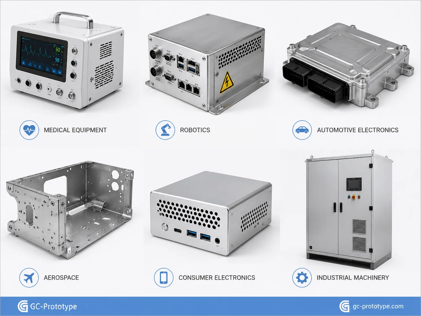
Medical Diagnostic Enclosure
A healthcare manufacturer uses stainless steel or powder-coated steel for a diagnostic-equipment enclosure. Continuous seams, smooth corners, gasketed doors, and reinforced equipment mounts support cleaning and serviceability.
The DFM strategy uses formed returns to stiffen large panels, standardized self-clinching hardware, and controlled weld locations away from visible surfaces. Door flanges are inspected for flatness before gasket installation.
Industrial Robot Control Cabinet
A robotics company requires a rigid cabinet with DIN rails, ventilation, cable glands, grounding studs, and removable service panels. Formed channels and ribs strengthen the structure without excessive thickness.
Laser cutting supports early design changes, while repeat production uses dedicated fixtures and standardized hardware to reduce assembly time.
Automotive Electronics Bracket
An automotive supplier develops laser-cut and bent brackets for sensor and control modules during pilot production. Once annual demand stabilizes, stamping is evaluated to reduce unit cost.
Critical mounting holes are dimensioned from a common datum, while non-critical openings use general fabrication tolerances.
Aerospace Equipment Tray
A lightweight aluminum tray uses formed flanges, lightening holes, and captive hardware. Critical interfaces are inspected from common datums.
Grain direction, bend radius, and alloy temper are reviewed before production to reduce cracking risk.
Consumer Electronics Chassis
A smart-hardware product uses a thin aluminum chassis with precise connector cutouts and a premium finish. Cosmetic surfaces are protected throughout forming and assembly.
Anodized surfaces, grounding areas, and hidden fasteners are defined during DFM so that appearance does not interfere with electrical or mechanical performance.
Industrial Machine Guard
An equipment manufacturer needs guards, doors, and panels in customized sizes. Laser cutting enables fast configuration changes without dedicated tooling.
Hinges, interlocks, handles, windows, and safety labels are incorporated into the digital manufacturing package to simplify assembly and installation.
Selecting a Sheet Metal Fabrication Supplier
A qualified supplier should support laser cutting, CNC punching, press-brake bending, hardware insertion, welding, grinding, surface treatment, assembly, and dimensional inspection. More importantly, the supplier should provide DFM feedback before production begins.
The RFQ package should include:
Solid 3D CAD models
Flat patterns when available
Dimensioned 2D drawings
Material grade and thickness
Prototype and production quantities
Bend-radius assumptions
Hardware and fastener lists
Weld symbols and standards
Surface-finish requirements
Cosmetic surface classifications
Dimensional inspection requirements
Packaging and delivery expectations
During supplier evaluation, ask how bend deductions are calibrated, how material substitutions are controlled, how weld distortion is managed, and whether coating is completed internally or through an approved partner. Confirm that hardware installation tools, inspection gauges, and packaging methods match the project.
A strong supplier should identify impossible bend sequences, distorted holes, incompatible inserts, excessive welds, coating conflicts, and tolerance risks before quoting. Transparent communication during DFM is often a better indicator of production reliability than the lowest initial unit price.
Questions to Ask Before Awarding a Project
Ask the supplier whether it maintains bend tables for each material and thickness, whether it can provide first-article reports, and how it controls revision changes. For welded enclosures, review fixture strategy and distortion limits.
For medical, aerospace, automotive, or other controlled industries, confirm traceability, inspection calibration, material certification, nonconformance handling, and approved finishing sources.
Frequently Asked Questions
What Is Sheet Metal Fabrication Best Used For?
It is well suited to enclosures, brackets, cabinets, panels, chassis, guards, trays, frames, and other parts requiring lightweight structural performance and scalable production.
Which Material Is Best for Medical Enclosures?
Stainless steel 304, 316L, powder-coated steel, and aluminum are common options. The correct material depends on cleaning chemicals, corrosion exposure, weight, structural load, and regulatory requirements.
How Is the Minimum Bend Radius Selected?
It depends on material grade, temper, thickness, grain direction, tooling, and forming method. Use a standard chart for early design and confirm the final value with the fabricator.
What Is the K-Factor?
The K-factor represents the location of the neutral axis through the material thickness and is used when calculating bend allowance and the flat pattern.
When Is Laser Cutting Better Than Stamping?
Laser cutting is usually preferable for prototypes, low-to-medium volumes, customized parts, and designs that may change. Stamping becomes attractive for stable high-volume production.
How Can Sheet Metal Cost Be Reduced?
Standardize materials and hardware, improve nesting, reduce bend setups, replace welding with formed or mechanical joints, and apply tight tolerances only to functional features.
Why Do Holes Distort Near Bends?
Material stretches and compresses during forming. Holes inside the deformation zone can elongate, tear, or shift toward the bend.
Should Welded Enclosures Be Designed as One Part?
Not always. Dividing an enclosure into practical panels can simplify cutting and forming, but excessive separate parts increase welding and assembly. The design should balance bend feasibility, weld length, appearance, and service requirements.
Can Powder Coating Affect Dimensions?
Yes. Coating thickness can affect tight slots, threaded features, hinge fits, electrical contacts, and mating surfaces. Critical areas may require masking or finish-condition dimensions.
What Files Are Needed for a Quote?
Provide STEP files, drawings, material and thickness, quantities, hardware, weld requirements, finish, tolerances, inspection needs, and delivery expectations.
Sheet metal fabrication provides a flexible and cost-effective route from early structural prototypes to repeat production. Its core advantages are short lead times, strong lightweight construction, broad material selection, scalable automation, and the ability to revise designs without rebuilding expensive molds.
The strongest projects combine practical bend radii, calibrated K-factors, sufficient hole offsets, standardized materials, compatible hardware, limited welding, realistic tolerances, and a process strategy matched to lifetime volume. Laser cutting and press-brake forming support NPI and flexible production, while hard-tool stamping can deliver lower recurring cost when demand and design stability justify the investment.
Scaling your structural enclosures from early-stage prototype to high-volume production requires practical DFM standards and smart process choices. Whether you are a Senior Mechanical Engineer designing healthcare hardware or a Sourcing Manager evaluating laser cutting vs stamping sheet metal cost, GC Prototype is your expert manufacturing partner.
Our capabilities include laser cutting, CNC punching, precision bending, welding, hardware insertion, powder coating, anodizing, assembly, dimensional inspection, rapid prototypes, and low-volume production.