Address:
Shenzhen Bao'an District Xinqiao Subdistrict Huangpu Community Huangpu East Ring Road No. 504 Shenzhen Yuan Industrial City Building C
Work Hours:
Monday to Friday: 9AM - 21PM
Weekend: 9AM - 21PM

Address:
Shenzhen Bao'an District Xinqiao Subdistrict Huangpu Community Huangpu East Ring Road No. 504 Shenzhen Yuan Industrial City Building C
Work Hours:
Monday to Friday: 9AM - 21PM
Weekend: 9AM - 21PM

3D Printing has become one of the most influential manufacturing technologies in modern product development. During New Product Introduction (NPI) and rapid prototyping, traditional CNC machining or injection molding often increases development time due to complex machining operations or expensive tooling. Industrial 3D Printing, also known as additive manufacturing, enables engineers to validate concepts, optimize designs, and manufacture highly complex geometries without tooling constraints. For Senior Mechanical Engineers, Product Designers, R&D Engineers, and Sourcing Managers, selecting the right printing process, engineering material, and production strategy is critical for balancing performance, lead time, and manufacturing cost.
This guide explores industrial additive manufacturing from an engineering perspective, covering material selection, process comparison, design optimization, quality control, and cost analysis. Whether your project involves medical devices, aerospace components, consumer electronics, robotics, or industrial automation equipment, understanding the strengths and limitations of different 3D printing technologies can significantly reduce product development risks while accelerating time-to-market.
Industry Applications & Material Innovation
Industrial additive manufacturing has evolved far beyond concept models. Today’s production-grade systems manufacture functional prototypes, bridge production parts, custom tooling, and even certified end-use components. The combination of advanced engineering polymers and high-performance metal alloys allows manufacturers to produce lightweight structures that would be impossible using conventional subtractive manufacturing.
Compared with traditional fabrication methods, industrial 3D Printing provides several unique advantages:
Zero tooling investment
Rapid design iteration
Complex internal geometries
Lightweight lattice structures
Shorter development cycles
Digital manufacturing workflow
Low-volume production flexibility
Reduced material waste
For companies developing hardware products, these advantages translate directly into lower engineering costs and faster commercialization.
Healthcare Engineering: Following 3d printing design guidelines for medical implants
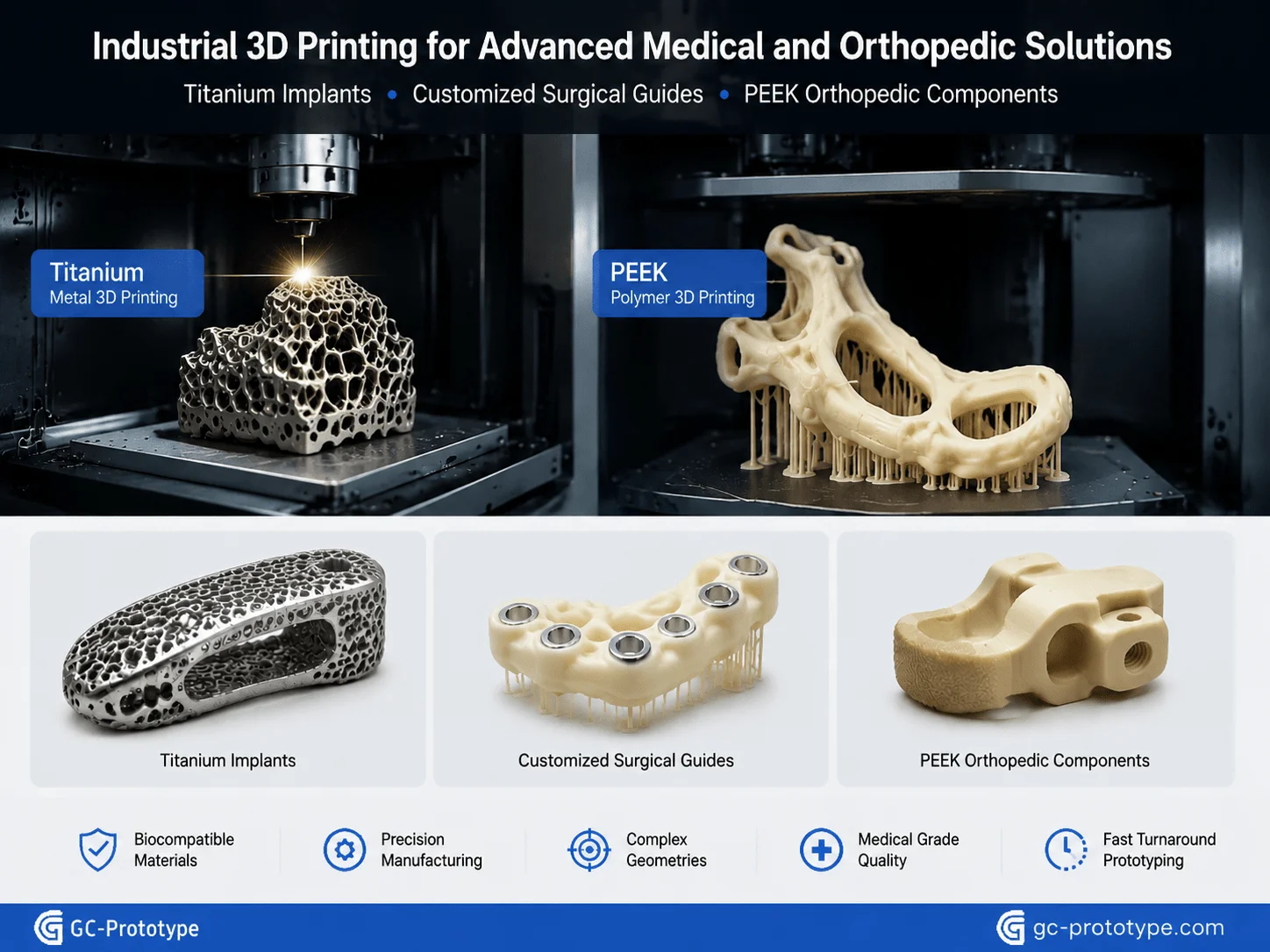
Following 3d printing design guidelines for medical implants has become increasingly important as additive manufacturing expands into medical devices, customized surgical tools, orthopedic implants, and patient-specific healthcare products. Unlike conventional machining, industrial 3D printing enables engineers to manufacture porous structures, lightweight implants, and anatomically optimized geometries that closely match patient requirements.
Among available materials, titanium alloy Ti6Al4V remains the preferred option for permanent orthopedic implants because of its exceptional strength-to-weight ratio, corrosion resistance, fatigue performance, and excellent biocompatibility. For temporary surgical instruments and medical housings, engineering thermoplastics such as PEEK, ULTEM, and medical-grade nylon provide outstanding chemical resistance while maintaining dimensional stability during sterilization.
One of the most significant innovations enabled by additive manufacturing is the use of lattice structures. Instead of manufacturing solid implants, engineers can design controlled porous architectures that encourage bone ingrowth while reducing implant weight. These cellular structures closely mimic the mechanical properties of natural bone, reducing stress shielding and improving long-term implant stability.
For example, spinal cages, cranial plates, acetabular cups, and maxillofacial implants frequently incorporate lattice geometries that cannot be manufactured using CNC machining. Additive manufacturing also allows surgeons to receive patient-specific implants produced directly from CT scan data, significantly improving surgical accuracy and reducing operation time.
Medical product development also requires compliance with strict regulatory standards. Engineers must consider:
Biocompatibility requirements
Sterilization compatibility
Surface roughness control
Powder contamination prevention
Traceability documentation
Mechanical validation
Material certification
Dimensional verification
Material selection is equally important. While titanium dominates implant manufacturing, PEEK has become increasingly popular for spinal implants due to its radiolucency and bone-like elastic modulus. Stainless steel remains widely used for surgical instruments, whereas medical-grade photopolymers support anatomical models and surgical planning.
Beyond implants, hospitals increasingly use industrial 3D printing to manufacture customized surgical guides. These disposable guides improve drilling accuracy, reduce surgical complexity, and shorten operating room time without requiring expensive tooling.
As healthcare shifts toward personalized medicine, industrial additive manufacturing will continue enabling patient-specific treatments while lowering development costs for medical device manufacturers.
Aerospace & Defense: Leveraging metal 3d printing for aerospace prototyping
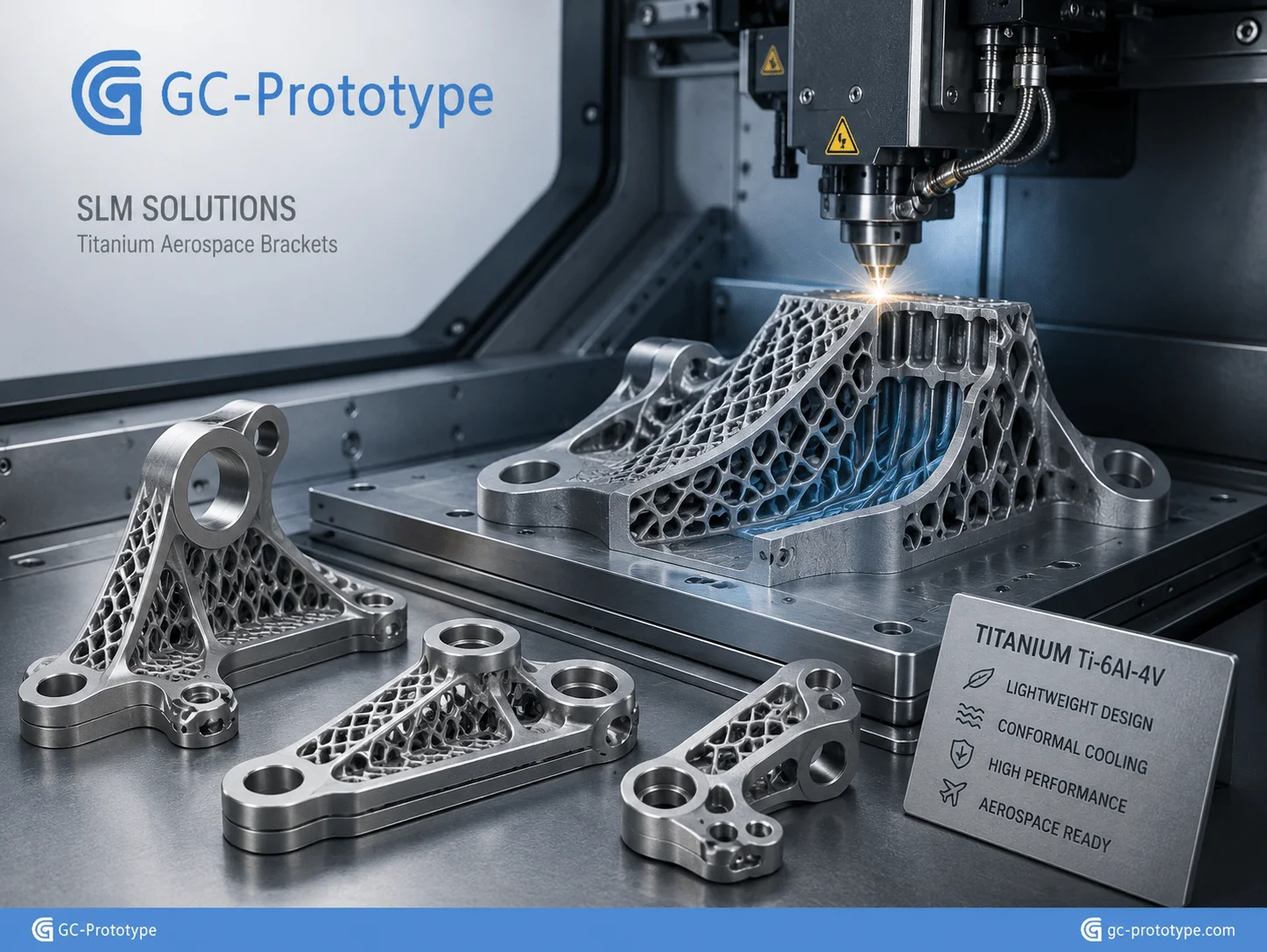
Leveraging metal 3d printing for aerospace prototyping allows aerospace manufacturers to dramatically shorten development cycles while producing lighter, stronger, and more efficient flight components. Conventional machining often struggles to manufacture highly complex internal passages, topology-optimized geometries, and lightweight lattice structures. Metal additive manufacturing eliminates many of these limitations.
Technologies such as Selective Laser Melting (SLM) and Direct Metal Laser Sintering (DMLS) enable engineers to manufacture aerospace-grade components directly from powdered titanium, aluminum, Inconel, stainless steel, and cobalt-chromium alloys.
Instead of assembling multiple machined components using welding or fasteners, engineers can consolidate dozens of individual parts into one optimized printed component. This reduces assembly time, lowers inventory costs, improves reliability, and minimizes potential failure points.
One of the biggest advantages is conformal cooling. Traditional machining cannot easily produce curved internal cooling channels following complex surfaces. Metal additive manufacturing creates these channels directly inside the component, significantly improving thermal management for turbine blades, rocket engines, aerospace tooling, and high-performance heat exchangers.
Weight reduction remains another major benefit. Every kilogram removed from an aircraft contributes to lower fuel consumption and reduced operating costs. Engineers therefore increasingly apply topology optimization software before printing structural brackets, satellite supports, UAV components, and propulsion system hardware.
Common aerospace applications include:
Engine brackets
Satellite structures
Heat exchangers
Fuel manifolds
Hydraulic components
UAV airframe parts
Rocket engine components
Conformal cooling inserts
Lightweight structural supports
Unlike production tooling, aerospace prototype development often requires frequent design revisions. Traditional manufacturing may require weeks of machining and fixture preparation after every CAD revision. Industrial metal printing reduces iteration cycles from weeks to days, allowing engineering teams to validate performance much earlier during product development.
Material certification remains essential. Aerospace manufacturers typically require full traceability for powder batches, process parameters, heat treatment, and post-processing inspection. Components often undergo CT scanning, coordinate measuring machine (CMM) inspection, tensile testing, fatigue testing, and nondestructive evaluation before qualification.
As aerospace systems become increasingly lightweight and performance-driven, industrial metal additive manufacturing continues transforming how engineers approach prototype validation, flight testing, and low-volume production.
Process Trade-offs & Quality Specifications
Selecting the right additive manufacturing process is not simply a matter of choosing the newest technology. Each industrial 3D Printing process offers unique advantages in dimensional accuracy, surface finish, mechanical properties, material compatibility, production speed, and overall manufacturing cost. For Product Designers, Mechanical Engineers, and Procurement Managers, understanding these trade-offs ensures the selected technology aligns with both technical requirements and commercial objectives.
While SLA delivers exceptional cosmetic quality, SLS offers greater design freedom for functional engineering parts. Metal printing technologies such as SLM and DMLS provide unmatched structural performance but require significantly higher equipment investment and post-processing. Selecting the wrong process can increase production costs, delay product development, or create unnecessary finishing operations.
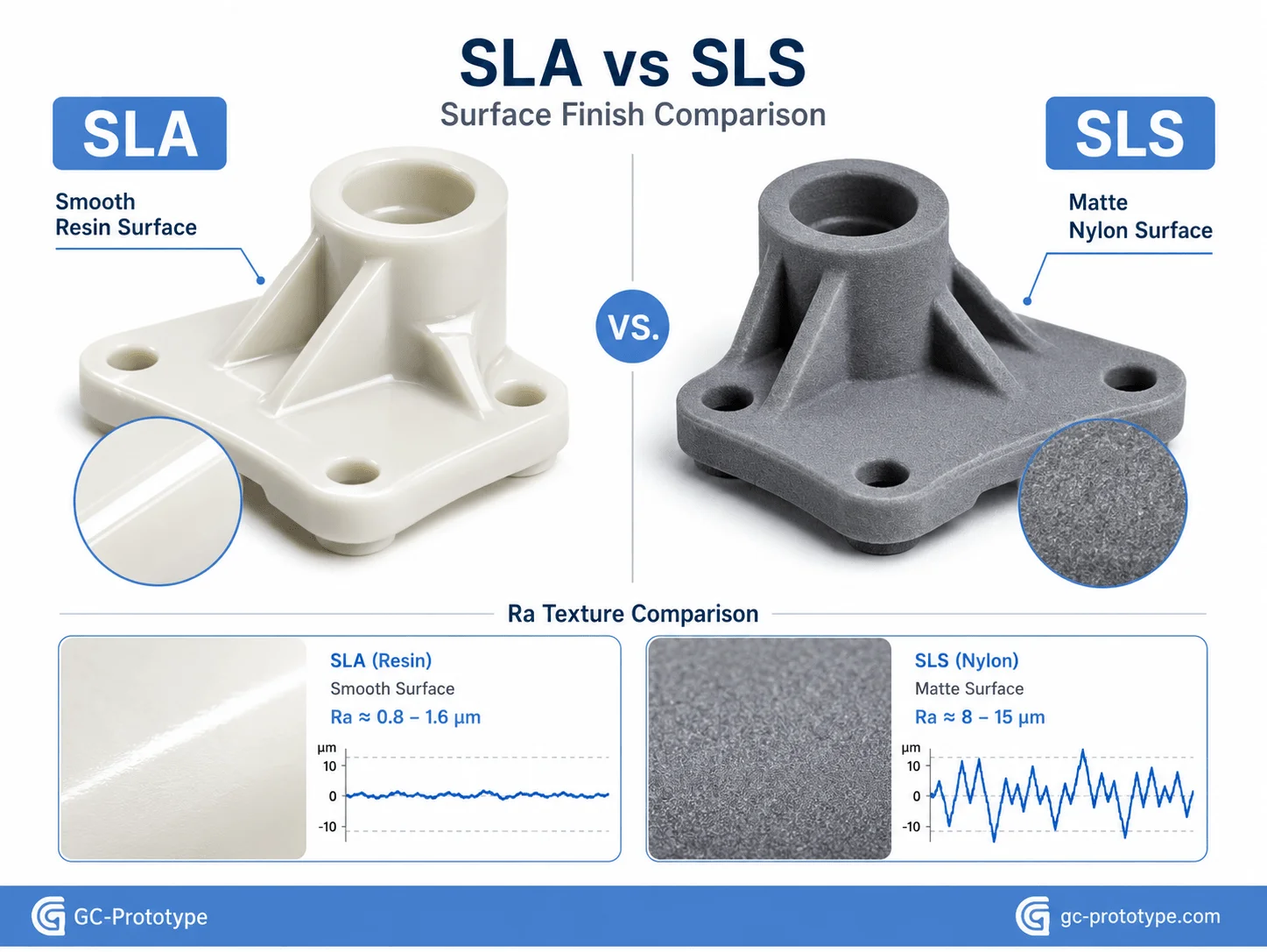
Aesthetic & Surface Control: Comparing sls vs sla 3d printing surface roughness
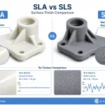
Comparing sls vs sla 3d printing surface roughness is one of the most common challenges faced by industrial designers and product development teams. Although both technologies belong to industrial additive manufacturing, they produce significantly different surface characteristics, mechanical performance, and post-processing requirements.
SLA (Stereolithography) builds parts by curing liquid photopolymer resin layer by layer using a UV laser. Since each layer is extremely thin—typically between 25 and 100 microns—the resulting surfaces are exceptionally smooth. This makes SLA an ideal choice for appearance models, transparent components, ergonomic studies, and products requiring high cosmetic quality.
Typical applications include:
Medical device housings
Consumer electronic enclosures
Transparent optical components
Cosmetic product prototypes
Functional marketing samples
Precision assembly verification
In contrast, SLS (Selective Laser Sintering) fuses nylon powder using a high-powered laser. Because the material consists of fine powder particles, finished parts exhibit a naturally matte texture and higher surface roughness. However, SLS offers one significant advantage: parts are supported by surrounding powder during printing, eliminating the need for support structures.
This allows engineers to manufacture:
Complex internal channels
Moving assemblies
Interlocking mechanisms
Lightweight lattice structures
Functional snap-fit components
Production-grade engineering prototypes
A direct comparison highlights the strengths of each technology:
| Feature | SLA | SLS |
| Surface Finish | Excellent, smooth | Slightly rough, matte |
| Typical Ra | 1–3 μm (after finishing) | 8–15 μm (before finishing) |
| Accuracy | Excellent | Very good |
| Support Structures | Required | Not required |
| Best Materials | Photopolymer Resin | Nylon PA12, PA11, TPU |
| Mechanical Strength | Moderate | Excellent |
| Transparent Parts | Yes | No |
| Complex Internal Geometry | Moderate | Excellent |
| Functional Testing | Limited | Excellent |
Surface finish directly affects downstream manufacturing. SLA parts typically require only light sanding, polishing, or UV coating before presentation. Transparent SLA components may even achieve near-optical clarity after polishing.
SLS parts, meanwhile, often undergo bead blasting, tumbling, dyeing, vapor smoothing, or media finishing depending on cosmetic requirements. Although these processes increase production time slightly, they greatly improve appearance while maintaining excellent mechanical performance.
When selecting between SLA and SLS, engineers should evaluate several factors simultaneously:
Functional load
Required appearance
Assembly tolerance
Surface roughness
Environmental resistance
Chemical exposure
Production quantity
Lead time
For cosmetic prototypes presented to investors or customers, SLA generally provides the superior visual result. For engineering validation, snap-fit testing, mechanical assemblies, and low-volume functional production, SLS often becomes the preferred solution.
Financial Breakdown: industrial 3d printing vs injection molding cost
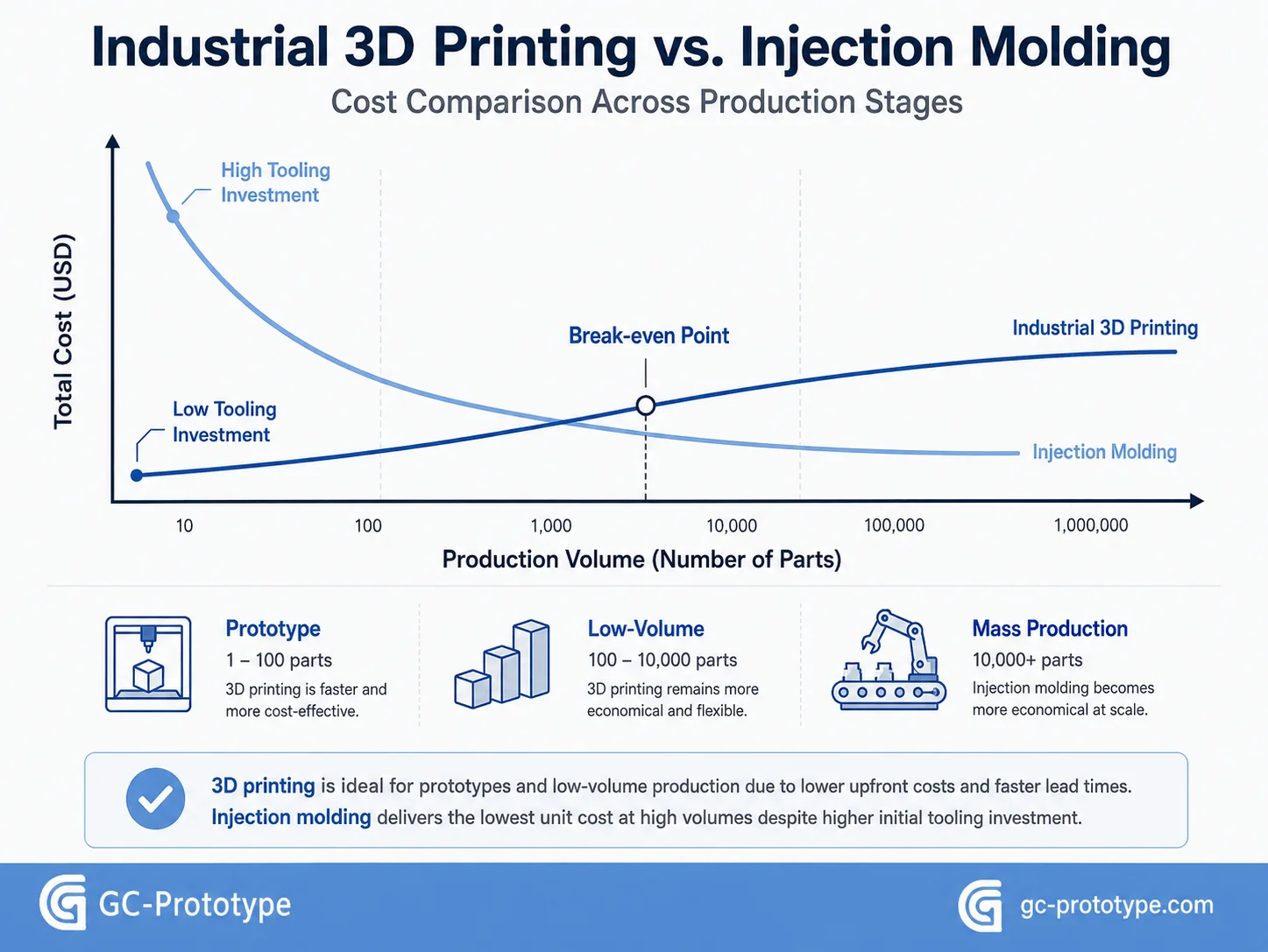
Understanding industrial 3d printing vs injection molding cost is essential for Procurement Managers, Founders, Product Managers, and Strategic Buyers planning new product launches. Although injection molding remains the most economical process for high-volume production, industrial additive manufacturing often provides significantly lower total project costs during prototype development and low-volume manufacturing.
The biggest financial difference lies in tooling.
Injection molding requires custom steel or aluminum molds, which often cost anywhere from several thousand to tens of thousands of dollars depending on part complexity, cavity count, and expected production volume. Tool manufacturing alone may take four to eight weeks before the first molded component is produced.
Industrial 3D Printing eliminates this investment entirely.
Because parts are manufactured directly from digital CAD data, companies can begin production immediately after design approval. This dramatically reduces financial risk during early product development when design revisions are frequent.
Typical cost comparison:
| Production Quantity | Industrial 3D Printing | Injection Molding |
| 1–10 Parts | Lowest Total Cost | Extremely Expensive |
| 10–50 Parts | Usually Lower | Tooling Dominates Cost |
| 50–100 Parts | Often Competitive | Mold Cost Still High |
| 100–300 Parts | Depends on Geometry | Break-even Begins |
| 500–1000+ Parts | Higher Unit Cost | Significantly Lower |
The break-even point varies depending on:
Part size
Material
Wall thickness
Mold complexity
Number of design revisions
Surface finish
Assembly requirements
For example, imagine a medical device housing requiring five design iterations before regulatory testing.
Using injection molding, every major geometry change may require expensive mold modifications, increasing both cost and lead time.
Using industrial 3D Printing, engineers simply update the CAD model and begin printing again—often within hours. This flexibility allows engineering teams to optimize product performance before investing in permanent tooling.
Beyond tooling savings, additive manufacturing also reduces inventory costs.
Rather than stocking thousands of molded components, manufacturers can adopt digital inventory strategies by storing CAD files and producing parts only when demand exists. This minimizes warehouse expenses while improving responsiveness to customer orders.
Another important consideration is product lifecycle.
Many industrial products—including laboratory instruments, automation equipment, robotics systems, and aerospace hardware—never reach the production volumes required to justify injection molds. For these applications, industrial additive manufacturing may remain the most economical production method throughout the product’s entire lifecycle.
Cost optimization should therefore evaluate the total cost of ownership, including:
Tooling investment
Prototype revisions
Engineering labor
Material utilization
Production lead time
Inventory carrying costs
Product obsolescence risk
Time-to-market impact
Organizations that calculate only unit price frequently overlook these hidden costs. For most hardware startups and low-volume industrial products, faster commercialization often creates far greater business value than marginal reductions in manufacturing cost.
Essential DFM Rules for Industrial 3D Printing
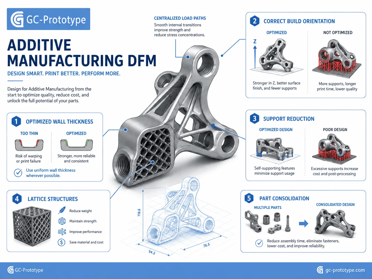
Successful industrial 3D Printing begins long before a model enters the printer. Engineers who understand Design for Additive Manufacturing (DfAM) can reduce printing failures, minimize post-processing, improve mechanical performance, and significantly lower production costs. Unlike traditional machining or molding, additive manufacturing introduces unique design opportunities—but it also comes with process-specific constraints.
A well-designed component requires fewer support structures, shorter build times, less material consumption, and minimal secondary finishing. By considering wall thickness, build orientation, support generation, tolerances, and part consolidation during the design stage, manufacturers can maximize both quality and cost efficiency.
Optimize Wall Thickness for Strength and Printability
Wall thickness is one of the most important design parameters in additive manufacturing. Extremely thin walls may warp, crack, or fail during printing, while excessively thick sections increase build time, material usage, and residual stress.
Recommended design practices include:
Maintain uniform wall thickness whenever possible.
Avoid abrupt transitions between thick and thin sections.
Add ribs instead of increasing overall wall thickness.
Use hollow structures where weight reduction is required.
Reinforce load-bearing areas using lattice or internal rib structures.
For polymer printing, thin cosmetic covers may only require a few millimeters of thickness, whereas structural brackets subjected to mechanical loading require considerably more reinforcement. Metal printed components should also avoid unnecessary solid masses, as these increase thermal stress and distortion during the build process.
Instead of designing solid blocks, engineers increasingly use topology optimization software to remove unnecessary material while preserving structural performance.
Minimize Support Structures Through Smart Orientation
Support structures stabilize overhanging features during printing, but they also increase production cost.
Additional supports require:
More material
Longer print time
Manual removal
Surface finishing
Additional inspection
Good build orientation can dramatically reduce these costs.
For example, rotating a component by 30–45 degrees often minimizes unsupported overhangs while improving surface quality. Large flat surfaces should generally be positioned to reduce internal stress and warping.
Different technologies require different support strategies:
| Process | Support Requirement |
| SLA | Required for most overhangs |
| SLS | No support required (powder supports part) |
| FDM | Required for large overhangs |
| SLM / DMLS | Required for heat dissipation and stability |
Engineers should evaluate build orientation not only for print success but also for post-processing accessibility. Removing supports from internal channels or confined cavities may be impossible after printing.
Design with Manufacturing Tolerances in Mind
Although industrial 3D Printing delivers excellent dimensional accuracy, every technology has practical tolerance limits.
Factors affecting dimensional accuracy include:
Material shrinkage
Layer thickness
Thermal expansion
Powder characteristics
Resin curing
Build orientation
Post-processing
Critical dimensions such as bearing seats, precision bores, sealing surfaces, and threaded interfaces often require secondary machining after printing.
Rather than specifying unnecessarily tight tolerances across an entire part, engineers should:
Apply precision tolerances only to functional features.
Allow clearance for mating components.
Machine only critical interfaces.
Incorporate adjustment features where appropriate.
This hybrid manufacturing approach significantly reduces overall production costs while maintaining engineering performance.
Consolidate Multiple Components into One Printed Assembly
One of additive manufacturing’s greatest advantages is part consolidation.
Traditional manufacturing often requires numerous machined components connected by fasteners, welding, or adhesives.
Industrial 3D Printing allows designers to combine these individual parts into one integrated component.
Benefits include:
Reduced assembly labor
Fewer fasteners
Lower inventory
Improved reliability
Reduced leak paths
Better structural stiffness
Simplified supply chain
Examples include:
Hydraulic manifolds
Aerospace brackets
Medical instrument housings
Robotic end effectors
Industrial automation fixtures
By eliminating unnecessary joints, engineers improve both manufacturing efficiency and long-term product reliability.
Design Checklist Before Sending Parts to Production
Before releasing CAD files for manufacturing, engineering teams should verify:
✓ Appropriate wall thickness
✓ Proper build orientation
✓ Minimal support structures
✓ Functional tolerances defined
✓ Drainage holes for hollow components
✓ Powder removal access (metal & SLS)
✓ Thread strategy reviewed
✓ Material selected for application
✓ Surface finish requirements defined
✓ Post-processing requirements identified
✓ Inspection requirements documented
Completing this checklist helps reduce redesign cycles while improving first-pass manufacturing success.
Material Selection for Industrial 3D Printing
Selecting the correct engineering material is just as important as choosing the printing technology itself. Material properties directly influence strength, thermal resistance, dimensional stability, chemical compatibility, surface finish, and long-term durability.
| Material | Typical Process | Main Advantages | Typical Applications |
| Standard Resin | SLA | Excellent appearance | Cosmetic prototypes |
| Tough Resin | SLA | Impact resistance | Functional prototypes |
| PA12 Nylon | SLS | High strength & durability | Mechanical components |
| TPU | SLS | Flexible | Seals, gaskets |
| ABS | FDM | Low cost | Engineering models |
| ULTEM | FDM | High temperature resistance | Aerospace |
| Titanium Ti6Al4V | SLM | High strength & biocompatibility | Medical & Aerospace |
| Aluminum AlSi10Mg | SLM | Lightweight | Robotics & Automotive |
| Stainless Steel 316L | SLM | Corrosion resistance | Industrial equipment |
Material selection should always be based on the actual operating environment rather than material cost alone. Factors such as temperature, humidity, UV exposure, fatigue loading, sterilization, chemical resistance, and expected service life all influence long-term performance.
For example, a cosmetic prototype intended for customer evaluation may only require SLA resin, while a functional robotic bracket subjected to continuous loading may be better suited to PA12 nylon or aluminum metal printing.
Engineers should also consider post-processing compatibility. Certain materials can be polished, dyed, painted, vapor smoothed, anodized, or machined after printing to improve both aesthetics and functionality.
Quality Control & Inspection
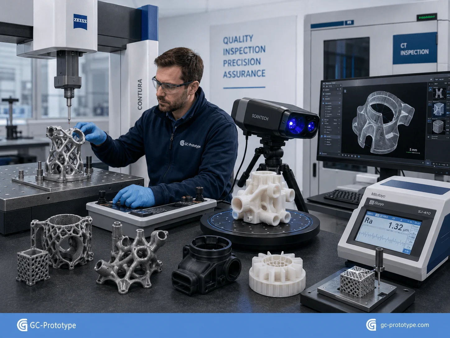
Industrial additive manufacturing requires a comprehensive quality assurance process to ensure dimensional consistency and repeatable mechanical performance.
Typical inspection methods include:
Coordinate Measuring Machine (CMM)
3D laser scanning
CT scanning for internal geometry
Tensile testing
Surface roughness measurement
Material certification
Density verification
Visual inspection
For metal printed parts, additional post-processing such as stress relief, heat treatment, HIP (Hot Isostatic Pressing), machining, and polishing may be required before final inspection.
Manufacturers supplying aerospace or medical industries typically maintain complete traceability records, documenting powder batches, machine parameters, operator information, and inspection results throughout the production process.
Cost Optimization Strategies for Industrial 3D Printing
Although industrial 3D Printing eliminates tooling costs, optimizing total manufacturing cost requires careful engineering decisions throughout the product development cycle. Material selection, build orientation, nesting strategy, post-processing, and production planning all contribute to the final cost per part.
One of the most effective ways to reduce cost is to match the manufacturing process to the product’s lifecycle stage. During concept validation and engineering verification, additive manufacturing provides unmatched flexibility by allowing rapid design iterations without additional tooling investment. Once the design stabilizes and annual production volume increases, manufacturers should reassess whether conventional processes such as CNC machining, vacuum casting, or injection molding become more economical.
Several practical strategies help improve return on investment:
1.Select the most suitable printing technology based on functional requirements rather than appearance alone.
2.Minimize unnecessary support structures to reduce both material consumption and post-processing time.
3.Optimize build orientation to shorten print duration and improve dimensional consistency.
4.Combine multiple components into a single printed assembly whenever possible.
5.Standardize engineering materials across product families to simplify procurement and inventory.
6.Apply secondary machining only to critical functional surfaces instead of the entire component.
7.Consider hybrid manufacturing by combining additive manufacturing with CNC machining for precision features.
Another important consideration is production batching. Printing multiple parts simultaneously often reduces machine idle time and improves equipment utilization, particularly for SLS and metal powder bed fusion technologies. Proper nesting strategies can significantly lower the cost per component without affecting quality.
Engineers should also evaluate the total cost of ownership rather than focusing solely on unit price. Factors such as shorter lead times, faster design validation, lower inventory requirements, and reduced engineering risk frequently provide greater long-term value than marginal reductions in manufacturing cost.
Choosing the Right Industrial 3D Printing Partner
Selecting an experienced manufacturing partner is as important as selecting the correct printing technology. A qualified supplier should offer comprehensive engineering support from initial DFM review through production and quality assurance.
When evaluating a supplier, consider the following capabilities:
Industrial-grade SLA, SLS, MJF, FDM, SLM, and DMLS equipment
Broad selection of certified engineering materials
In-house CNC machining for secondary operations
Surface finishing and painting services
Dimensional inspection using CMM and 3D scanning
Material traceability and quality documentation
Rapid prototyping and low-volume production expertise
Engineering consultation for Design for Additive Manufacturing (DfAM)
A reliable supplier should also provide proactive design recommendations before production begins. Experienced engineers can identify unsupported geometries, excessive wall thickness, poor build orientation, unnecessary material usage, or tolerance conflicts early in the design process. These recommendations help reduce manufacturing costs while improving overall product performance.
For companies serving medical, aerospace, robotics, automotive, and industrial automation markets, supplier experience with regulated industries and demanding quality standards is especially valuable.
Frequently Asked Questions
What is the best industrial 3D printing process for functional prototypes?
There is no universal answer. SLA is ideal for high-accuracy cosmetic models, while SLS offers superior durability for mechanical testing. Metal printing technologies such as SLM and DMLS are preferred for high-strength aerospace and medical applications.
Is industrial 3D printing suitable for low-volume production?
Yes. Industrial 3D Printing is highly cost-effective for prototypes, bridge production, customized products, and low-volume manufacturing because it eliminates expensive tooling and allows rapid design modifications.
When should manufacturers switch from 3D printing to injection molding?
The transition depends on product complexity, tooling investment, annual production volume, and expected design stability. Once designs are finalized and production volumes increase substantially, injection molding often provides a lower cost per unit despite its higher initial tooling expense.
Which engineering materials are commonly used in industrial additive manufacturing?
Common materials include PA12 nylon, TPU, ABS, engineering resins, PEEK, ULTEM, titanium alloys, aluminum alloys, stainless steel, Inconel, and cobalt-chromium. Material selection should always be based on mechanical performance, environmental conditions, and regulatory requirements.
How accurate is industrial 3D printing?
Industrial additive manufacturing can achieve excellent dimensional accuracy, but actual tolerances depend on the printing process, material, part geometry, and post-processing. Critical interfaces are often finish-machined to achieve tighter engineering tolerances.
How can engineers reduce 3D printing costs?
The most effective strategies include optimizing part orientation, minimizing support structures, reducing unnecessary material volume, consolidating multiple components into a single design, selecting appropriate materials, and applying precision machining only where functionally required.
Industrial 3D Printing has transformed modern product development by enabling engineers to manufacture complex, lightweight, and highly customized components with unprecedented speed and flexibility. Compared with traditional manufacturing methods, additive manufacturing significantly shortens development cycles, reduces tooling investment, accelerates design validation, and supports cost-effective low-volume production.
Whether developing patient-specific medical devices, lightweight aerospace structures, robotic components, industrial automation equipment, or consumer electronics, selecting the appropriate printing technology, engineering material, and DfAM strategy is essential for achieving the optimal balance between performance, quality, lead time, and cost.
As industrial additive manufacturing continues to evolve, companies that integrate 3D Printing into their product development workflow will gain a competitive advantage through faster innovation, lower development risk, and greater manufacturing agility.
Get Expert Industrial 3D Printing Support
Whether you need rapid prototypes, functional engineering parts, or low-volume production, GC Prototype provides comprehensive industrial 3D Printing solutions tailored to your product requirements.
Our capabilities include SLA, SLS, MJF, FDM, SLM, DMLS, CNC post-machining, precision inspection, surface finishing, and engineering DFM support for industries including medical devices, aerospace, robotics, automotive, industrial automation, and consumer electronics.