Address:
Shenzhen Bao'an District Xinqiao Subdistrict Huangpu Community Huangpu East Ring Road No. 504 Shenzhen Yuan Industrial City Building C
Work Hours:
Monday to Friday: 9AM - 21PM
Weekend: 9AM - 21PM

Address:
Shenzhen Bao'an District Xinqiao Subdistrict Huangpu Community Huangpu East Ring Road No. 504 Shenzhen Yuan Industrial City Building C
Work Hours:
Monday to Friday: 9AM - 21PM
Weekend: 9AM - 21PM

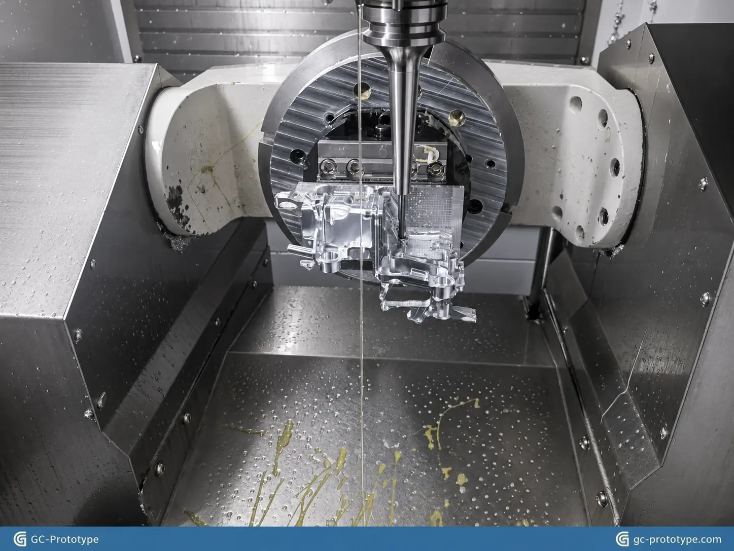
Precision CNC turned parts are essential for mechanical assemblies that require accurate diameters, controlled geometric relationships, and consistent dimensional quality. From precision shafts and bushings to threaded connectors and small-diameter pins, cnc precision turned parts must meet more than basic dimensional requirements. Features such as concentricity, runout, cylindricity, and surface finish can directly influence assembly performance.
Choosing the right manufacturing and inspection approach for cnc precision turning parts helps OEM engineers reduce fit problems, improve production consistency, and control manufacturing costs.
For engineering teams and procurement professionals, finding reliable precision turned components manufacturers involves evaluating machining capabilities, dimensional inspection methods, material control, and production consistency.
At GC-Prototype, we support custom CNC machining projects from CAD review and prototype manufacturing to functional validation, low-volume production, and ongoing manufacturing support. This guide explains the key factors involved in manufacturing, inspecting, and sourcing precision CNC turned components.
Not every CNC turned component requires the same level of accuracy. A general-purpose spacer may only need basic dimensional control, while a precision shaft used in a rotating assembly may require tighter diameter tolerances, controlled runout, and specific surface characteristics.
The difference lies in the component’s intended function and its relationship with other parts in the assembly.
Dimensional accuracy refers to whether individual measurements, such as external diameter, internal diameter, and overall length, fall within specified limits.
Geometric accuracy describes the form, orientation, and relationship between different features.
For example, a shaft may have an acceptable external diameter but still create assembly problems if its rotating surface has excessive runout.
Both types of accuracy should be considered when designing and manufacturing precision turned components.
For OEM manufacturers, producing one acceptable prototype is only part of the requirement.
The supplier must also demonstrate an appropriate process for maintaining dimensional consistency across the agreed production quantity.
Factors affecting repeatability include:
Cutting tool wear.
Workpiece material variation.
Machine condition and thermal stability.
Workholding and setup consistency.
Machining parameters.
Measurement methods.
A suitable inspection plan helps identify dimensional variation before it affects the final assembly.
Not all dimensions have equal importance.
For a precision shaft, the bearing diameter and shoulder position may be critical, while an external nonfunctional surface may have less demanding requirements.
Engineering drawings should clearly identify critical dimensions, mating interfaces, datum references, and applicable geometric tolerances.
This helps manufacturers allocate machining and inspection resources where they have the greatest impact on product performance.
Dimensional and geometric tolerances are among the most important considerations in precision CNC turning.
An overly restrictive tolerance can increase machining and inspection costs without improving the component’s actual function. Conversely, insufficient tolerance control may cause alignment problems, excessive clearance, or assembly interference.
External diameters and internal bores directly affect how turned components fit with mating parts.
Common examples include:
Shaft diameters for bearing assemblies.
Internal diameters for bushings and sleeves.
Shoulder diameters for locating components.
Overall length for axial positioning.
Step dimensions for mechanical interfaces.
For precision turned components, tolerances should be assigned according to the required fit, operating conditions, and assembly function.
Coaxial relationships are important when multiple cylindrical features must share a common axis.
For example, a shaft may contain several stepped diameters that need to align correctly with bearings, seals, or connected components.
If these features are not properly aligned, the assembled component may experience uneven contact or rotational problems.
When specifying geometric controls, engineers should select appropriate GD&T requirements based on the function of the part. Position and runout controls may be more appropriate than relying on a general concentricity requirement.
Runout measures the variation of a surface relative to a specified datum axis as the part rotates.
Circular runout evaluates variation at an individual circular cross-section.
Total runout evaluates variation across the entire controlled surface during rotation.
These controls are particularly relevant for:
Rotating shafts.
Precision spindles.
Bearing journals.
Cylindrical coupling components.
Mechanical transmission parts.
Excessive runout can contribute to vibration, uneven contact, and reduced assembly performance.
Roundness describes how closely a circular cross-section matches a perfect circle.
Cylindricity controls the overall form of a cylindrical surface along its length.
Both characteristics may be important for components requiring consistent contact, accurate positioning, or controlled rotational performance.
GD&T uses datum references to establish the measurement framework for a component.
For example, a shaft may use its primary cylindrical surface as a datum axis, while other features are controlled relative to that reference.
Tolerance stack-up occurs when dimensional variations across multiple components accumulate within an assembly.
Reviewing these relationships during the design stage can help prevent unnecessary tolerance requirements and improve manufacturing feasibility.
| Critical Feature | What It Controls | Potential Assembly Problem |
| Outside Diameter | Shaft or mating diameter | Incorrect fit |
| Inside Diameter | Bore size | Bearing or shaft fitting issues |
| Coaxial Relationship | Alignment of related features | Misalignment |
| Circular Runout | Surface variation during rotation | Vibration or uneven contact |
| Total Runout | Variation across a rotating surface | Excessive rotational variation |
| Cylindricity | Overall cylindrical form | Poor contact or fit |
| Axial Length | Shoulder and spacing dimensions | Assembly interference |
Machining accuracy must be verified through appropriate measurement and inspection methods.
The inspection equipment should be selected according to the component’s geometry, dimensional requirements, and applicable engineering specifications.
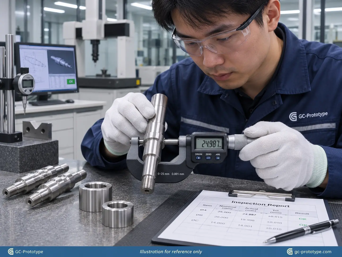
Outside micrometers are commonly used to measure shaft diameters and other external cylindrical dimensions.
They are useful for checking:
Shaft diameters.
Stepped diameters.
Pin dimensions.
External cylindrical surfaces.
Critical machining dimensions.
For measurements requiring higher repeatability, operators should follow consistent measurement procedures and account for instrument calibration and measurement conditions.
Internal bores can be measured using suitable bore gauges or air gauges.
These instruments are useful for evaluating:
Bearing bores.
Sleeve diameters.
Internal cylindrical features.
Precision mating holes.
Air gauging can be particularly useful for repetitive measurements of suitable precision bores during production inspection.
Roundness testers and appropriate runout measurement setups can help evaluate cylindrical form and rotational variation.
A component may have an acceptable average diameter but still fail its geometric requirements.
For this reason, dimensional measurement alone is not always sufficient for precision turned parts.
Coordinate Measuring Machines (CMMs) use a measuring probe to collect dimensional information from different locations on a component.
Depending on the measurement strategy and machine capability, CMM inspection can be used to evaluate:
Feature locations.
Diameter and length relationships.
Datum-related dimensions.
Hole positions.
Selected geometric tolerances.
Complex component geometry.
CMM inspection is particularly useful when a component contains multiple related features that must be evaluated against an engineering drawing.
However, specialized roundness or form measurement equipment may be more suitable for certain roundness and cylindricity requirements.
Surface finish can influence friction, sealing performance, and component contact.
A profilometer can be used to measure surface roughness when a numerical Ra requirement is specified.
Threaded components may require thread plug gauges or thread ring gauges to verify conformity with the specified thread standard.
| Inspection Equipment | Suitable Features | Inspection Purpose |
| Outside Micrometer | External diameter | Verify shaft dimensions |
| Bore Gauge | Internal diameter | Check bore size |
| Air Gauge | Suitable precision bores | Evaluate dimensional variation |
| Roundness Tester | Cylindrical surfaces | Measure roundness |
| CMM | Multiple related features | Verify dimensions and geometric requirements |
| Profilometer | Surface finish | Measure specified Ra |
| Thread Gauge | Internal and external threads | Verify thread conformity |
A reliable inspection process should connect each critical drawing requirement with an appropriate measurement method.
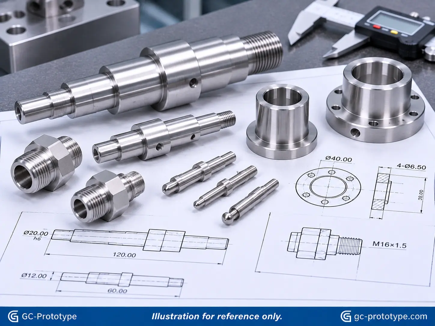
Precision turning supports a wide range of mechanical and industrial applications.
Although these components may share similar cylindrical geometries, their functional requirements and inspection priorities can be different.
Precision shafts and spindles are used in motors, transmission systems, industrial equipment, and rotating assemblies.
Important requirements may include:
Controlled external diameters.
Shoulder positioning.
Runout.
Straightness.
Surface finish.
Bearing fit.
For rotating applications, dimensional and geometric accuracy should be evaluated together.
Bushings and sleeves are commonly used to support shafts, maintain alignment, and control mechanical clearances.
Their critical features may include internal diameter, external diameter, length, and surface finish.
For spacers, axial length and end-face geometry may be more important than rotational characteristics.
Precision pins are used in positioning systems, mechanical assemblies, automation equipment, and electronic devices.
Small-diameter components may require careful control of diameter, length, straightness, and surface condition.
For slender parts, workpiece support and machining stability also influence dimensional consistency.
Threaded connectors and valve stems require accurate threads, mating diameters, and functional sealing surfaces where applicable.
The engineering drawing should identify the thread standard, pitch, engagement length, and any specific sealing requirements.
| Turned Component | Critical Features | Typical Inspection Focus |
| Precision Shaft | Diameter, runout, straightness | Micrometer / runout setup |
| Bushing | ID, OD, length | Bore gauge / micrometer |
| Spacer | Length, parallel faces | Dimensional inspection |
| Precision Pin | Diameter, roundness | Micrometer / roundness measurement |
| Threaded Connector | Thread, bore, sealing face | Thread gauge / bore gauge |
| Valve Stem | Diameter, runout, sealing surface | Dimensional and surface inspection |
The appropriate turning process depends on component geometry, dimensions, production quantity, and the required machining operations.
Conventional CNC turning is suitable for many cylindrical components, including shafts, bushings, spacers, and threaded parts.
It provides flexibility for prototype development and different production quantities.
Swiss-type turning is particularly suitable for small-diameter and slender components.
The workpiece support arrangement can help improve machining stability for appropriate geometries.
Typical applications include precision pins, miniature shafts, connectors, and small mechanical components.
Some precision turned components also require cross-holes, flats, slots, or milled features.
Mill-turn equipment or secondary milling operations may be suitable depending on the part geometry.
The goal is to maintain accurate relationships between turned and milled features while minimizing unnecessary setups.
| Process | Suitable Parts | Main Consideration |
| Conventional CNC Turning | General shafts and cylindrical parts | Flexible prototype production |
| Swiss Turning | Small and slender precision parts | Workpiece support and process stability |
| Mill-Turn | Turned parts with cross-holes and milled features | Multiple operations and datum control |
| Secondary Milling | Parts requiring additional flats or slots | Additional setup and alignment |
Selecting a suitable process during the engineering review can help reduce manufacturing complexity and improve dimensional consistency.
For OEM customers, quality control must extend beyond the first acceptable sample.
A reliable manufacturing arrangement should establish how critical dimensions are monitored throughout production.
First Article Inspection verifies whether the initial manufactured component meets the specified engineering requirements.
The inspection should focus on critical dimensions, geometric tolerances, material requirements, and surface finish.
The exact reporting format should be agreed upon between the buyer and supplier.
In-process inspection helps identify dimensional changes before they affect an entire production batch.
Typical checks may include:
External and internal diameters.
Overall length.
Thread dimensions.
Critical shoulder positions.
Selected geometric characteristics.
The inspection frequency should reflect the part’s criticality, process stability, and agreed quality plan.
Cutting tools gradually wear during machining.
Tool wear can influence dimensional accuracy, surface finish, and machining consistency.
Monitoring important dimensions and maintaining suitable tool replacement procedures helps reduce unexpected variation.
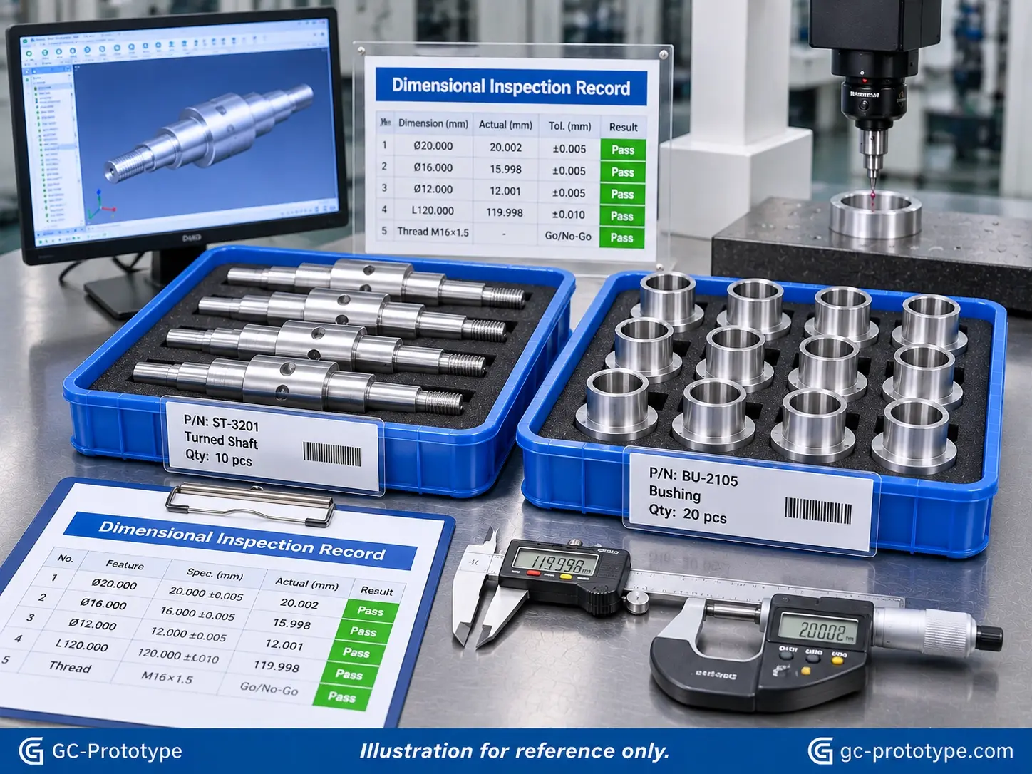
Final inspection verifies whether the finished components meet the agreed acceptance criteria.
Depending on the project, buyers may require:
Dimensional inspection reports.
Material certificates.
Surface finish records.
Thread inspection results.
Batch identification.
Nonconformance documentation, where applicable.
For international OEM projects, clear inspection documentation helps engineering and procurement teams review supplier performance.
The required level of traceability depends on the application, customer specifications, and industry requirements.
The cost of precision turned components depends on material selection, part geometry, tolerance requirements, machining time, inspection, and order quantity.
Understanding these factors can help buyers optimize designs without compromising functional requirements.
Tighter tolerances may require additional machining operations, more careful process control, and increased inspection time.
A practical approach is to apply tight tolerances only to dimensions that directly affect assembly or performance.
Different materials have different machining characteristics.
Material hardness, machinability, stock dimensions, and availability can all influence manufacturing costs.
Complex geometries involving deep holes, narrow grooves, and multiple diameters may also require additional machining time.
Projects requiring detailed dimensional reports, additional measurement procedures, and material documentation may involve higher inspection costs.
The buyer should identify these requirements during the quotation stage.
Prototype orders generally involve a different cost structure from repeat production.
Programming, setup, and initial inspection costs may represent a larger proportion of small orders.
Additional operations such as deburring, polishing, grinding, or plating may also affect the final price.
| Cost Factor | Cost Impact | Optimization Approach |
| Tight Tolerances | More machining and inspection | Apply tight tolerances only to critical features |
| Complex Geometry | More operations and setups | Simplify nonfunctional features |
| Difficult Material | Higher machining time | Select suitable material grades |
| Detailed Inspection | More measurement time | Define critical inspection points |
| Surface Finish | Additional finishing operations | Specify finish according to function |
| Production Quantity | Setup cost allocation | Plan appropriate batch sizes |
For OEM projects, reviewing the drawing and inspection requirements before production can help identify unnecessary costs and improve quotation accuracy.
Choosing the right supplier involves more than checking the quoted unit price.
Engineering and procurement teams should evaluate whether the manufacturer can produce the required component, verify its critical characteristics, and support the expected production arrangement.
Ask about the supplier’s available turning processes, workpiece dimensions, material experience, and ability to manufacture the required geometry.
Relevant questions include:
Can the supplier manufacture the required shaft diameter and length?
Are small-diameter components within its machining capabilities?
Can it produce internal and external threads?
Are secondary milling operations available when required?
A manufacturer should be able to explain how critical drawing requirements will be measured.
Ask which instruments are suitable for checking diameters, bores, runout, surface finish, and geometric relationships.
The measurement method should be appropriate for the required tolerance and component geometry.
For projects requiring specific material grades, ask whether the supplier can provide relevant material documentation.
Also clarify how production batches are identified and how nonconforming components are handled.
A capable manufacturing partner should understand the transition from initial CAD review to prototype samples, functional validation, and low-volume production.
This is particularly important for OEM customers developing new mechanical products or introducing revised components.
| Evaluation Item | What Buyers Should Verify |
| Machining Capability | Part diameter, length and geometry |
| Tolerance Control | Actual capability for critical features |
| Inspection Equipment | Suitable gauges and measurement systems |
| Quality Documentation | Inspection reports and material records |
| Production Flexibility | Prototype and batch quantities |
| Engineering Support | DFM and drawing review |
| Delivery | Agreed production and shipping schedule |
When comparing cnc turned components manufacturers and precision turned components manufacturers, prioritize verified manufacturing and inspection capabilities over general marketing claims.
A complete Request for Quotation (RFQ) helps suppliers understand the technical and commercial requirements of your project.
Providing the necessary information at the beginning can reduce clarification time and improve quotation accuracy.
Provide a 3D CAD model in STEP, STP, or IGES format.
Include a 2D engineering drawing showing critical dimensions, tolerances, geometric controls, and drawing revision.
Identify important diameters, bores, axial lengths, datum references, and geometric tolerances.
If certain dimensions directly affect assembly performance, clearly highlight them.
Specify the material grade, condition, and any required surface treatment.
Include surface roughness requirements when a numerical finish specification is necessary.
Provide prototype quantity, initial production quantity, estimated repeat demand, and required inspection documentation.
Also identify the destination country and target delivery schedule.
| RFQ Information | Recommended Details |
| 3D CAD | STEP / STP / IGES |
| 2D Drawing | PDF with revision |
| Material | Exact grade and condition |
| Critical Dimensions | Diameter, length, bore |
| GD&T | Datums, runout, position and form |
| Threads | Standard, pitch and fit |
| Surface Finish | Specified Ra |
| Quantity | Prototype and production quantities |
| Inspection | FAI and dimensional reports |
| Delivery | Destination and target schedule |
Providing these details allows the manufacturing team to review feasibility, select suitable machining methods, and prepare a more accurate quotation.
Achievable tolerances depend on material, component geometry, diameter, length, machine capability, workholding, and inspection methods. Rather than assuming one universal tolerance, buyers should provide their engineering drawings and identify critical dimensions for manufacturing review.
Concentricity describes the relationship between the median points of cylindrical features, while runout evaluates surface variation relative to a datum axis during rotation. They are different geometric controls. For many practical rotating-part applications, position or runout controls may be more suitable depending on the functional requirement.
Common inspection methods include micrometers for external diameters, bore gauges for internal dimensions, thread gauges for threaded features, roundness testers for circular form, and CMMs for selected dimensional and geometric relationships.
A CMM is useful when multiple features must be measured relative to defined datums, particularly when components contain complex geometries or several related dimensions. Specialized measuring equipment may be more appropriate for certain roundness, cylindricity, or surface finish requirements.
Common materials include aluminum alloys, stainless steel, carbon steel, brass, copper, titanium, and engineering plastics. The correct choice depends on mechanical strength, corrosion resistance, machinability, operating temperature, and application requirements.
A supplier generally needs a 3D CAD model, 2D engineering drawing, material specification, critical tolerances, surface finish requirements, order quantity, inspection requirements, and delivery information. Complete technical documentation helps improve quotation accuracy and manufacturing planning.
Finding a suitable supplier for precision CNC turned parts requires a combination of machining capability, engineering support, dimensional inspection, and consistent production planning.
GC-Prototype supports custom CNC machining projects for international B2B customers, from CAD review and prototype manufacturing to functional validation, low-volume pilot production, and ongoing mass production support.
Whether you need precision shafts, bushings, threaded connectors, small-diameter pins, or other custom turned components, our team can review your drawings and discuss suitable manufacturing solutions.
Send us your 3D CAD files and engineering drawings, together with:
Required material grade.
Initial production quantity.
Critical dimensions and GD&T requirements.
Surface finish specifications.
Inspection and documentation requirements.
Target delivery schedule.
Our engineering team can review your project requirements and provide feedback on manufacturing feasibility and quotation details.
Ready to manufacture your precision CNC turned components?