Address:
Shenzhen Bao'an District Xinqiao Subdistrict Huangpu Community Huangpu East Ring Road No. 504 Shenzhen Yuan Industrial City Building C
Work Hours:
Monday to Friday: 9AM - 21PM
Weekend: 9AM - 21PM

Address:
Shenzhen Bao'an District Xinqiao Subdistrict Huangpu Community Huangpu East Ring Road No. 504 Shenzhen Yuan Industrial City Building C
Work Hours:
Monday to Friday: 9AM - 21PM
Weekend: 9AM - 21PM

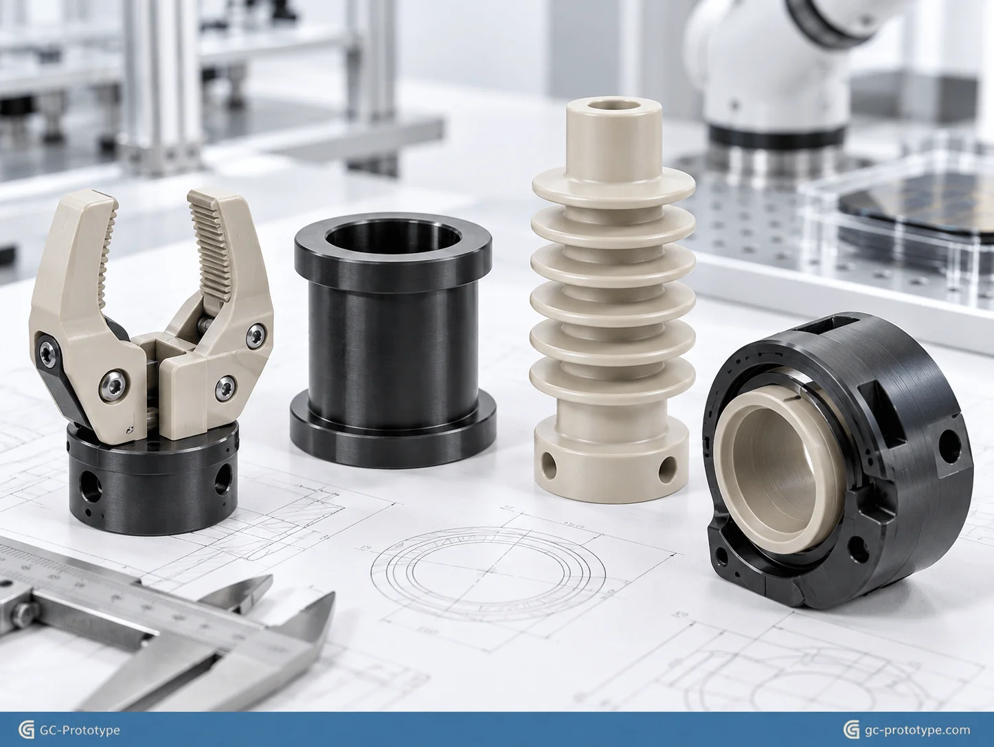
CNC machining PEEK tolerances for robotics has become increasingly important as robot developers move toward lighter, electrically insulating, low-friction, and chemically resistant mechanical systems. When engineering teams compare prototype PEEK machining vs 3D printing for robots, they are often trying to validate more than geometry: sliding fit, thread strength, dimensional stability, sterilization resistance, wear behavior, and high-temperature performance all matter. For demanding robotic applications where metals add weight or conductivity and common engineering plastics cannot provide sufficient creep or thermal resistance, machined PEEK offers a high-performance alternative.
PEEK, or polyether ether ketone, is a high-performance thermoplastic used in demanding mechanical, medical, semiconductor, aerospace, and automation applications. For Robotics Engineers, Senior Mechanical Engineers, Medical Robotics R&D teams, Process Engineers, and Sourcing Managers, its value comes from combining low density with mechanical strength, chemical resistance, electrical insulation, and strong performance across challenging operating environments.
However, PEEK is expensive and more difficult to machine dimensionally than ordinary plastics. Heat generated during cutting, residual stress in stock material, thin-wall deformation, moisture and thermal conditioning, and inappropriate tool geometry can all affect the final dimensions of a precision component.
This guide explains material selection, medical robotics applications, PEEK versus Delrin trade-offs, tolerance control, CNC versus additive manufacturing, DFM cost reduction, and sourcing strategy from CAD through prototype, functional validation, pilot production, and production support.
Why PEEK Is Valuable in Advanced Robotics
Robotic systems are becoming more compact, faster, cleaner, and more specialized. As a result, many engineering teams are discovering situations where neither conventional metals nor commodity plastics provide the right performance balance.
Metal components offer high stiffness and strength, but they may introduce:
Additional moving mass
Electrical conductivity
Corrosion concerns in specific environments
Lubrication requirements
Difficulties around magnetic or electrical isolation
General engineering plastics such as nylon, ABS, and standard acetal are lightweight and easy to process, but certain applications may exceed their practical limits in:
Temperature
Creep resistance
Chemical exposure
Dimensional stability
Repeated sterilization
PEEK provides another option for components such as:
Precision bushings
Wear pads
Robot gears
Sliding guides
Electrical insulators
Sensor supports
End-effector components
Medical robotic fixtures
Semiconductor automation parts
High-temperature positioning elements
PEEK should not automatically replace aluminum, stainless steel, or Delrin. Its higher raw-material cost means it makes the most sense when its engineering properties solve a real functional problem.
A well-designed PEEK component can sometimes eliminate lubrication, reduce weight, electrically isolate assemblies, resist aggressive chemicals, or continue operating where a lower-cost polymer would deform or wear too quickly.
That functional value—not simply the material name—should drive material selection.
PEEK Material Characteristics That Matter in Robotics
PEEK is attractive to robotics engineers because it combines several properties that are rarely found together in a thermoplastic.
Relevant characteristics include:
High mechanical strength for a polymer
Good creep resistance
Excellent chemical resistance
Low moisture absorption compared with many engineering plastics
Electrical insulation
Good wear behavior in appropriate grades
Resistance to repeated high-temperature exposure
Low density compared with metals
Different PEEK grades can also be modified with:
Carbon fiber
Glass fiber
Graphite
Other wear-enhancing fillers
Filled materials can increase stiffness, wear performance, or dimensional stability, but they also change machining behavior and may increase tool wear.
The correct grade should therefore be selected according to the real operating environment.
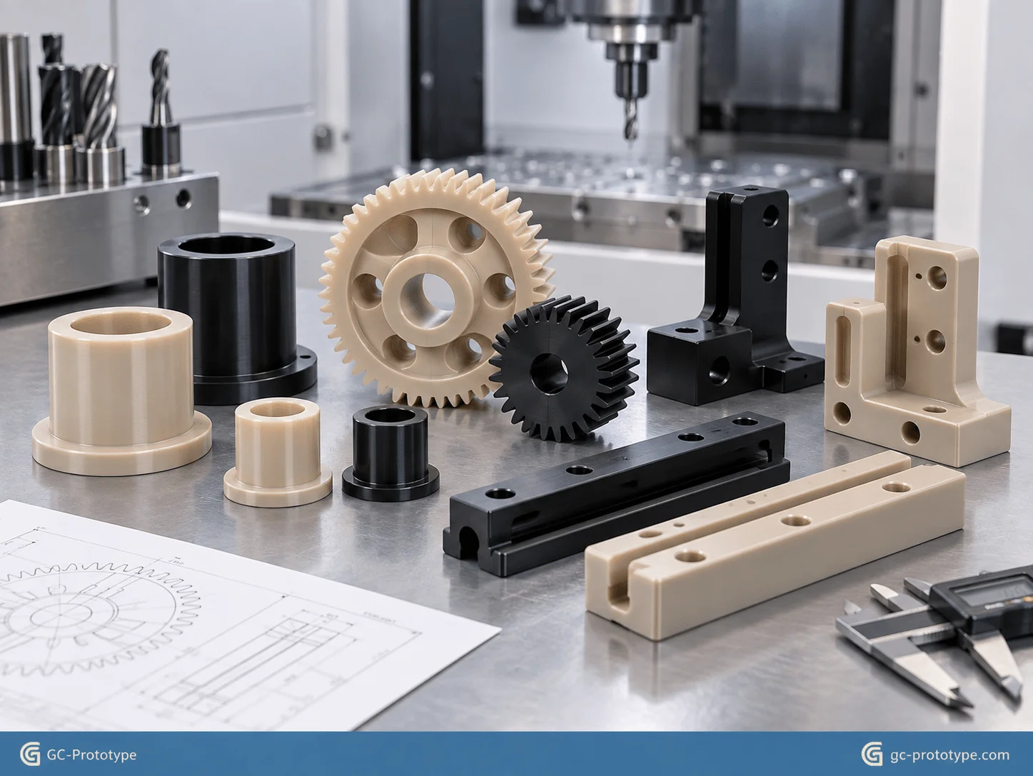
Material Performance & Robotics Applications
Sterile and Biocompatible Operations: custom machined PEEK parts for medical robotics
Custom machined PEEK parts for medical robotics are especially valuable where robotic components must combine low weight, chemical resistance, electrical insulation, cleanability, and resistance to repeated sterilization environments.
Potential applications include:
Surgical robotic end-effector components
Instrument guides
Endoscope-related housings and sleeves
Orthopedic power-tool components
Insulating fixtures
Robotic instrument positioning elements
Laboratory automation components
Medical robotics introduces requirements that are very different from those of ordinary industrial automation.
A component may need to tolerate:
Repeated cleaning
Steam sterilization
Chemical disinfectants
High mechanical loads
Tight assembly tolerances
PEEK is often considered for these environments because properly selected grades can provide excellent hydrolysis and chemical resistance.
However, engineers should not assume that any PEEK stock automatically satisfies medical or patient-contact requirements. Biocompatibility claims such as USP Class VI or ISO 10993 suitability depend on the exact material grade, supplier documentation, processing history, and intended use.
For regulated applications, the material specification should therefore identify the exact approved grade and required documentation before machining begins.
This is an important EEAT consideration because “PEEK” describes a polymer family—not a universal regulatory approval.
CNC Machining for Medical Robotic Components
CNC machining is particularly useful during medical robotics development because it can create prototype components directly from qualified stock material.
The process can provide:
Tight dimensional control
Smooth functional surfaces
Precision holes
Threads
Thin sections
Complex multi-axis geometry
Compared with molding, there is no dedicated mold investment during early development.
This enables engineering teams to move rapidly through:
CAD → Prototype → Functional Test → Design Revision
before investing in production tooling.
For components that require repeated sterilization validation, a machined prototype also provides more representative physical performance than an appearance-only model made from a lower-temperature plastic.
PEEK vs Delrin for Robotic Motion Components
Tribological Performance: PEEK vs Delrin for robotic gears and bushings
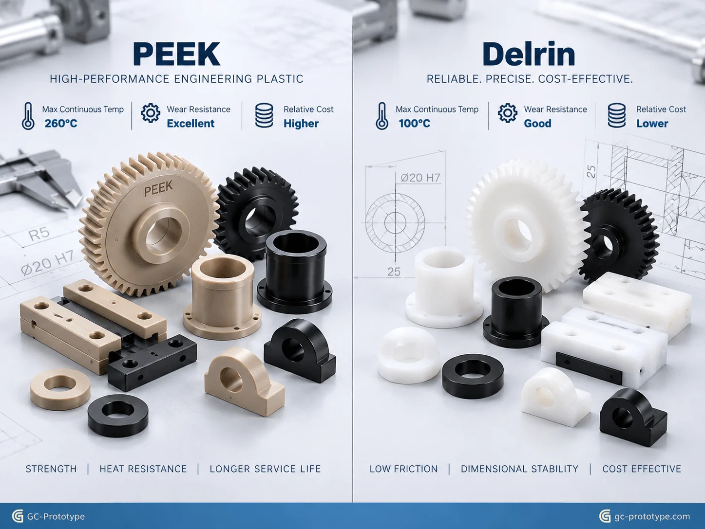
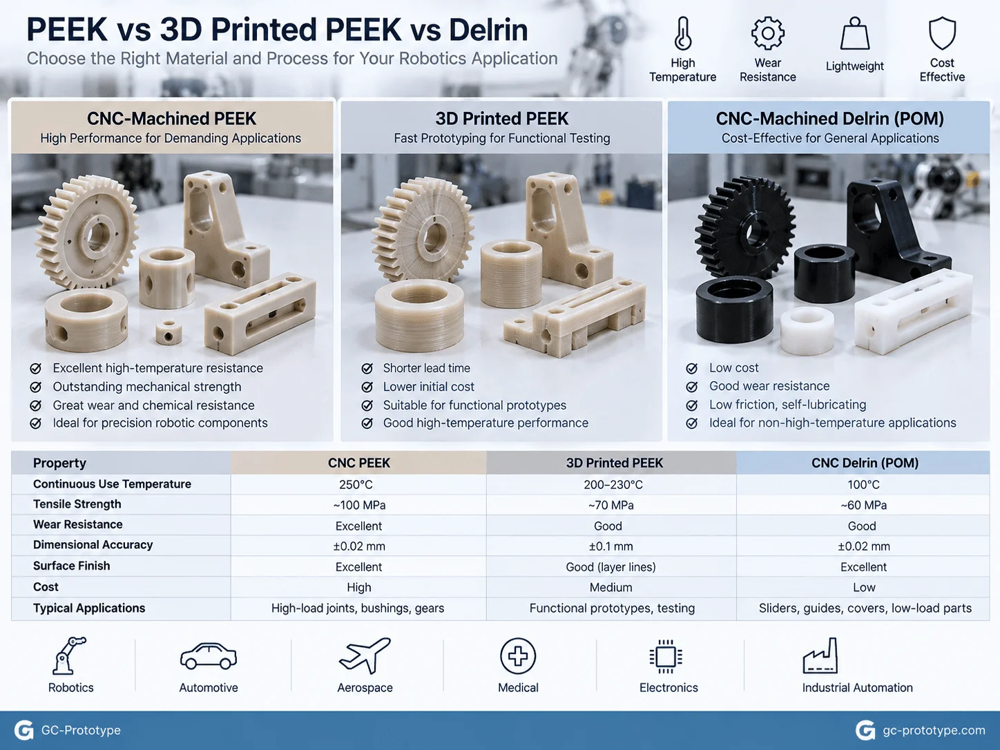
Evaluating PEEK vs Delrin for robotic gears and bushings is important because both materials can work well in sliding and rotational applications, but they serve different performance levels.
Delrin, commonly used to describe acetal or POM materials, is widely used for:
Bushings
Gears
Rollers
Guides
Low-friction mechanisms
It provides excellent machinability and relatively low cost.
PEEK is significantly more expensive, but its advantages become important where the application involves:
Higher temperature
Higher mechanical loading
Aggressive chemicals
Repeated sterilization
Long-duration creep resistance
| Engineering Factor | PEEK | Delrin / POM |
|---|---|---|
| Material Cost | High | Lower |
| Machinability | Good but demanding | Excellent |
| High-Temperature Performance | Excellent | Moderate |
| Creep Resistance | Excellent | Good |
| Chemical Resistance | Excellent | Good |
| Wear Performance | Excellent in suitable grades | Excellent for many general applications |
| Moisture Sensitivity | Low | Low |
| Precision Robotics Use | Severe environments | General-purpose motion components |
For a lightly loaded robot guide operating at room temperature, Delrin may be the more economical engineering choice.
For a high-load bushing operating near a heat source or in repeated sterilization cycles, PEEK may provide greater lifecycle value.
Reinforced PEEK for High-Load Robotics
Robotics engineers may also evaluate carbon-fiber, glass-fiber, or wear-modified PEEK grades.
Carbon-fiber-reinforced PEEK can offer:
Higher stiffness
Better dimensional stability
Lower thermal expansion in selected directions
Glass-filled PEEK can increase stiffness and dimensional control in certain applications.
Wear-modified grades may incorporate carbon or graphite to support sliding applications.
Potential robotic uses include:
High-load bushings
Precision guides
Wear rings
Robot gearing
Semiconductor handling equipment
However, reinforced grades can be more abrasive to cutting tools. Tool selection and machining parameters must account for the filler system.
The best material is therefore not always the highest-performance grade. Procurement and engineering teams should select the lowest-cost material that safely meets the actual operating requirements.
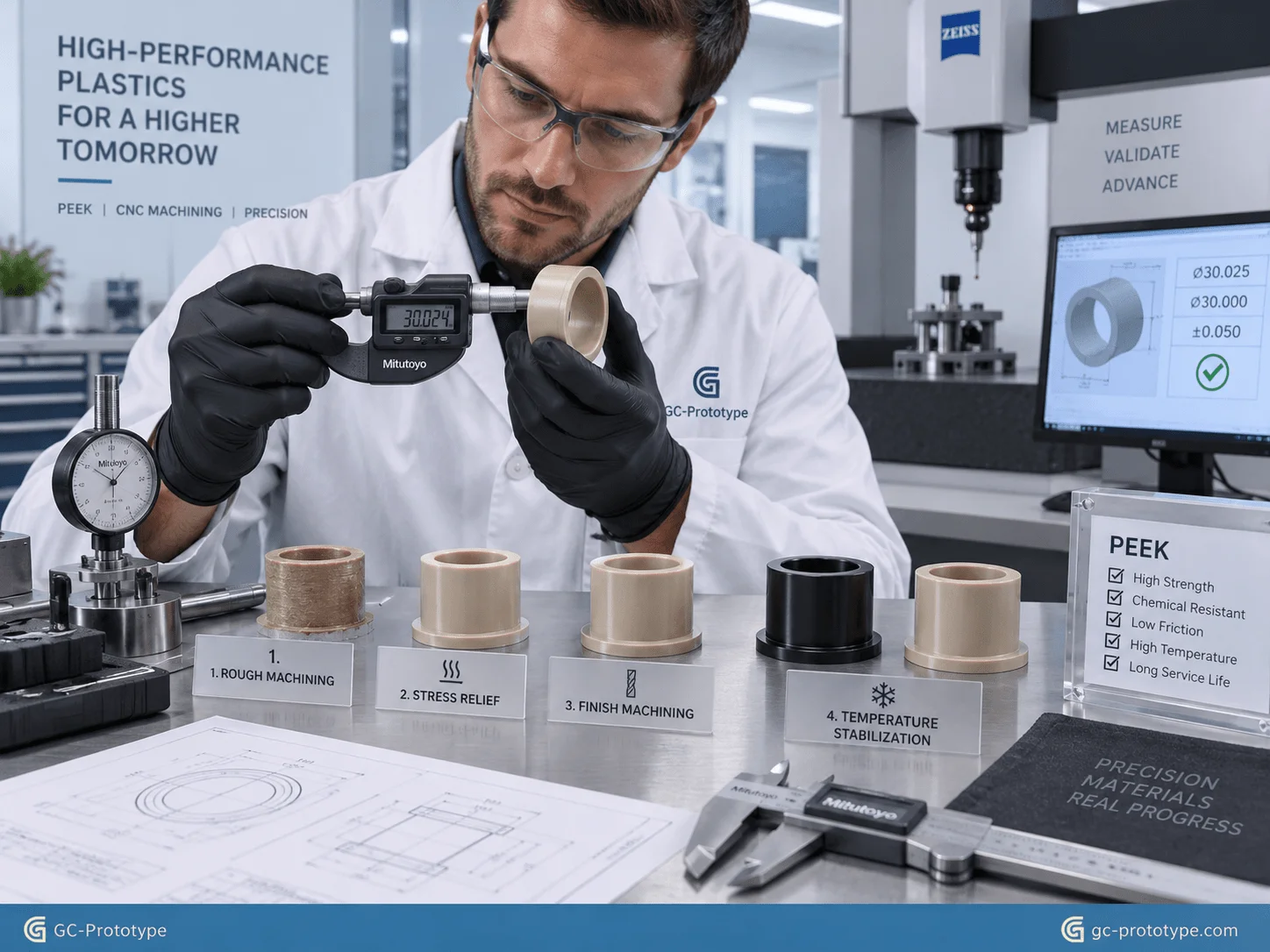
Precision Tolerances & Dimensional Stability
Dimensional Stability: Controlling cnc machining PEEK tolerances for robotics
Controlling cnc machining PEEK tolerances for robotics requires a different approach from machining aluminum or stainless steel.
PEEK has relatively low thermal conductivity compared with metals. During cutting, heat can remain concentrated around the machining zone.
If cutting heat is not controlled properly, the component may:
Expand during machining
Move after unclamping
Distort after material removal
Measure differently after temperature stabilization
Residual stress in extruded or molded stock can also become important when large quantities of material are removed.
For this reason, a component that measures correctly immediately after machining may shift slightly after it returns to thermal equilibrium.
Stress-Relief Annealing Strategy
For demanding precision parts, an intermediate stress-relief process may help maintain dimensional stability.
A typical strategy can include:
1.Rough machining the stock
2.Leaving material on critical surfaces
3.Stress-relief conditioning or annealing when required
4.Allowing the part to stabilize
5.Finish machining critical features
6.Performing final inspection under controlled conditions
The exact heat-treatment cycle should follow the recommendations for the specific PEEK grade and stock supplier. Applying a generic annealing cycle to every grade can create unnecessary risk.
This approach is particularly useful for:
Large asymmetric parts
Deep pockets
Thin-wall components
Tight sliding interfaces
Using Sharp Cutting Tools
PEEK machines cleanly when appropriate tooling is used.
Sharp cutters help reduce:
Cutting heat
Burr formation
Surface tearing
Material deformation
Tool geometry should support clean shearing rather than pushing or rubbing the polymer.
For reinforced PEEK, more wear-resistant tooling may be needed because carbon or glass fibers can increase abrasion.
Temperature-Controlled Inspection
Precision polymer measurement should account for temperature.
A part that is warm immediately after machining may not represent its stabilized final dimension.
For selected robotic sliding interfaces, ±0.01 mm-level tolerances may be achievable under suitable conditions, but this should not be applied indiscriminately to every feature. The outline specifically identifies ±0.01 mm as a target for critical robotic fits when appropriate process controls are used.
Critical features might include:
Sliding guide width
Precision bushing bore
Bearing interface
Alignment hole
Less critical external profiles can use broader tolerances.
This reduces machining and inspection cost without compromising function.
Moisture and Conditioning Considerations
PEEK has relatively low moisture absorption, but precision polymer parts should still be inspected and used under defined environmental conditions when dimensional variation is critical.
Engineering drawings can identify:
Inspection temperature
Functional fit requirement
Surface finish
Environmental assumptions
This is especially important when a component will move between machining, inspection, assembly, and a controlled robotics environment.
CNC-Machined PEEK vs 3D-Printed PEEK
Mechanical Integrity: prototype PEEK machining vs 3D printing for robots
Comparing prototype PEEK machining vs 3D printing for robots requires engineers to identify exactly what the prototype needs to prove.
Both technologies have value.
High-temperature additive manufacturing can produce complex PEEK geometry without machining large amounts of expensive stock. CNC machining, however, starts from solid stock and avoids the layer-by-layer structure associated with FDM-style processes.
For 1–20 functional robotic prototypes, the choice should be driven by test requirements.
| Evaluation Factor | CNC-Machined PEEK | 3D-Printed PEEK |
|---|---|---|
| Material Density | Solid stock | Process-dependent |
| Layer Interfaces | None | Present in layer-based processes |
| Tight Tolerances | Excellent | Often needs secondary machining |
| Surface Finish | High | Usually requires finishing |
| Complex Internal Geometry | Limited by tool access | Excellent |
| Thread Strength | Strong | Orientation/process dependent |
| Low Quantity | Excellent | Excellent |
| Material Waste | Higher | Lower |
| Functional Validation | Excellent | Application-dependent |
High-Torque and Shear Testing
Robotic parts may be exposed to:
High torque
Shear loading
Repeated fastening
Long-duration sliding
A machined PEEK part from homogeneous stock can provide highly consistent mechanical behavior for such testing.
Layer-based additive manufacturing may introduce anisotropy depending on:
Build orientation
Layer bonding
Thermal history
Printing parameters
This does not mean printed PEEK is inherently unsuitable. It means engineers should understand whether the printed material’s directional properties represent the intended final component.
Airtight and Sealing Applications
Some robotic applications include:
Pneumatic channels
Vacuum handling systems
Fluid pathways
For these components, porosity and surface condition can affect leakage.
Machining from dense stock can simplify functional validation of sealing surfaces and threaded ports.
If additive manufacturing is selected, leak testing and post-processing may become more important.
When 3D Printing Is the Better Choice
PEEK additive manufacturing may be attractive for:
Highly complex internal channels
Low-load concept parts
Shapes that would waste large amounts of expensive stock
Rapid geometry experimentation
A practical development workflow may therefore use both technologies:
3D Printing → Geometric Validation → CNC PEEK → Functional Validation → Production Process Selection
The goal is not to declare one technology universally superior. The goal is to use each where it provides the best engineering information for the money spent.
Prototype Cost Analysis for PEEK Robotics Components
PEEK is significantly more expensive than common engineering plastics, so material utilization has a major effect on prototype cost.
The total cost of a machined PEEK component may include:
Raw stock
Setup
CNC programming
Rough machining
Stress relief
Finish machining
Inspection
Scrap risk
For a small, simple bushing, machine time may dominate.
For a large component machined from an oversized block, raw-material waste may become one of the largest cost drivers.
Example Process Comparison
| Factor | PEEK CNC Machining | PEEK 3D Printing | Delrin CNC Machining |
|---|---|---|---|
| Raw Material Cost | High | High | Lower |
| Tight Precision | Excellent | Moderate without secondary work | Excellent |
| Complex Internal Geometry | Limited | Excellent | Limited |
| Prototype Functional Realism | High | Process-dependent | High for lower-demand environments |
| Material Waste | Higher | Lower | Higher |
| Best Fit | Critical functional validation | Complex geometries | Cost-sensitive general robotics |
For sourcing teams, the correct decision should consider total engineering cost rather than only quote price.
If a more expensive machined prototype provides reliable high-load, sealing, or dimensional data that prevents a redesign later, the additional prototype cost can be justified.
Procurement Strategy & DFM Guidelines
Engineering DFM Checklist: Reducing PEEK Material Waste and Machining Costs
PEEK cost control begins in CAD.
Because raw stock is expensive, a small change in component proportions can substantially change the amount of material required.
Design Around Standard Stock Sizes
Whenever possible, design the component around available:
Rod diameters
Plate thicknesses
Tube sizes
For example, designing a cylindrical component slightly larger than a common stock diameter may force the supplier to purchase the next significantly larger size.
This increases both raw material consumption and machining time.
A procurement-aware DFM review can identify this problem before the drawing is released.
Avoid Unnecessarily Deep Blind Holes
Deep blind holes are difficult in many materials, but they are particularly undesirable in expensive plastic components when they also require deep threading.
Potential problems include:
Chip evacuation
Tap breakage
Thread damage
Additional cycle time
Where possible:
Use through holes
Reduce unnecessary thread depth
Provide adequate tool access
Apply Tight Tolerances Selectively
A drawing that applies ±0.01 mm everywhere may dramatically increase cost.
Instead, classify features into:
Critical Fits
Examples:
Precision bushings
Sliding surfaces
Bearing interfaces
General Geometry
Examples:
Covers
Non-functional walls
Cable clearances
Only critical interfaces should carry demanding tolerance requirements.
Avoid Excessively Thin Walls
Thin PEEK sections can move during machining and after unclamping.
Maintaining practical wall thickness helps:
Improve machining stability
Reduce scrap risk
Maintain dimensional consistency
If lightweighting is required, engineers can use controlled pockets and ribs rather than extremely thin unsupported walls.
Consider Multi-Part Designs
A single highly complex PEEK component may require a large, expensive block of stock.
Sometimes a modular assembly can significantly reduce material waste.
However, splitting a component introduces:
Fasteners
Alignment features
Assembly labor
The best decision depends on whether material savings outweigh assembly complexity.
Robotics Application Scenarios
Medical Robotic End Effector
A surgical robotics team needs a lightweight electrically insulating gripper component capable of repeated cleaning and sterilization evaluation.
A qualified PEEK grade is CNC machined to create:
Precision mounting holes
Smooth contact surfaces
Thin lightweight geometry
Functional testing evaluates:
Sterilization durability
Mechanical stiffness
Assembly accuracy
Semiconductor Wafer Handling Robot
A clean automation system requires low-friction, chemically resistant mechanical components.
Machined PEEK can be evaluated for:
Guides
Bushings
Insulating brackets
Wear components
Filled PEEK grades may be considered where stiffness and wear resistance are priorities, subject to contamination requirements.
High-Temperature Industrial Robot
A robot operating near a thermal process needs polymer components that maintain performance beyond the practical operating range of ordinary acetal.
PEEK may be evaluated for:
Cable supports
Electrical isolators
Bushings
Sensor brackets
Self-Lubricating Robotic Joint Bushing
A compact joint requires a low-friction bushing without conventional grease in the target operating environment.
Engineers compare PEEK and Delrin based on:
Load
Speed
Temperature
Wear
Cost
CNC prototypes allow both materials to be tested under the same mechanical conditions before production selection.
From CAD to Prototype and Production Support
A strong PEEK manufacturing strategy should follow the complete product-development lifecycle.
CAD & DFM
At the beginning of the project, engineers evaluate:
Geometry
Material grade
Tolerances
Stock size
Tool access
Environmental requirements
This is the most cost-effective stage for identifying unnecessary material waste or unrealistic tolerances.
Prototype Sample
The first machined parts allow engineering teams to evaluate:
Fit
Assembly
Friction
Wear
Electrical isolation
Sterilization or chemical performance
Functional Validation
The next stage tests parts under realistic conditions.
Depending on the robot, this may include:
Repeated motion
Load testing
Elevated temperature
Chemical exposure
Sterilization
Leak testing
Low-Volume Pilot Production
Once the design becomes stable, a small pilot batch can be used to evaluate:
Process repeatability
Inspection strategy
Assembly workflow
Cost consistency
Production Support
After validation, the manufacturing route can be optimized according to volume and component complexity.
Some components may remain CNC machined, while others may transition to:
Injection molding
Compression molding
Alternative manufacturing processes
GC Prototype supports the development path from CAD → prototype sample → functional validation → low-volume pilot production → production support, helping engineering and sourcing teams maintain continuity as the product matures.
Frequently Asked Questions About PEEK Machining for Robotics
Why is PEEK used in robotics?
PEEK combines low weight, mechanical strength, chemical resistance, electrical insulation, wear performance, and high-temperature capability, making it useful for demanding functional robotic components.
Is PEEK better than Delrin for robot gears and bushings?
Not always. Delrin is usually more economical and performs very well in many general-purpose motion systems. PEEK becomes more attractive where temperature, chemical exposure, creep resistance, or severe loading justifies the additional material cost.
Can PEEK be machined to ±0.01 mm?
Selected critical features can potentially be controlled around ±0.01 mm when geometry, stock condition, stress management, machining strategy, temperature control, and inspection capability support it. It should not be specified universally across an entire component.
Why is stress-relief annealing used for PEEK?
Removing large amounts of material can release residual stresses in the stock. Intermediate stress relief may improve dimensional stability before final precision machining on demanding parts.
Is PEEK suitable for medical robotics?
PEEK can be appropriate for certain medical robotics applications, but the exact material grade and supporting compliance documentation must match the intended use. Engineers should not assume every PEEK grade is biocompatible or suitable for patient contact.
Can PEEK survive autoclave sterilization?
Certain PEEK grades are well suited to repeated high-temperature steam exposure, but suitability must be confirmed for the exact grade, sterilization cycle, geometry, and regulatory requirements.
Is CNC-machined PEEK stronger than 3D-printed PEEK?
Machined PEEK comes from solid stock and does not contain layer interfaces. Printed PEEK performance depends heavily on the additive process, build orientation, and processing conditions. The better option depends on the test requirement.
Why is PEEK machining expensive?
Cost comes from expensive raw material, material waste, precision machining time, stress-management operations, specialized tooling, and inspection requirements.
How can PEEK machining cost be reduced?
Use standard stock sizes, minimize unnecessary material removal, avoid deep blind threaded holes, apply tight tolerances only to functional interfaces, and review the CAD model before machining.
What files should be provided for a PEEK quotation?
Provide:
STEP or other 3D CAD model
2D drawing
Exact PEEK grade
Quantity
Critical tolerances
Surface finish requirements
Environmental or sterilization requirements
Inspection expectations
This allows the supplier to evaluate material, machining strategy, and cost accurately.
Build More Reliable Robotic Systems with Precision PEEK Machining
Advanced robotics increasingly requires materials that do more than provide basic structural support.
A high-performance robotic component may need to be:
Lightweight
Electrically insulating
Low friction
Wear resistant
Chemically stable
Dimensionally precise
Suitable for high-temperature operation
PEEK can meet many of these requirements when the material grade, machining process, and component design are selected correctly.
For Medical Robotics Engineers, PEEK can support lightweight sterilizable components when the correct qualified grade and compliance documentation are used. For Mechanical Engineers, precision-machined PEEK can provide stable bushings, guides, gears, and insulating structures. For Procurement Managers, the primary challenge is controlling the cost of an expensive material without compromising critical functional performance.
The most successful strategy starts before machining.
Design around standard stock sizes. Identify truly critical tolerances. Account for thermal and residual-stress behavior. Compare PEEK with Delrin where lower-cost materials may be sufficient. Use additive manufacturing when complex geometry provides a genuine advantage, and use CNC-machined stock when dimensional accuracy, dense material, threads, sealing, or mechanical reliability are the priority.
GC Prototype supports the complete development journey from CAD design to prototype samples, functional validation, low-volume pilot production, and production support.
Validating high-stress self-lubricating parts or medical-grade robotic components shouldn’t put your development schedule at risk through thermal deformation, unstable tolerances, or layer-related failures. Whether you are a Senior Mechanical Engineer optimizing tight-tolerance PEEK bushings or a Sourcing Manager evaluating PEEK vs Delrin machining costs, GC Prototype provides professional engineering support and precision multi-axis plastic machining.