Address:
Shenzhen Bao'an District Xinqiao Subdistrict Huangpu Community Huangpu East Ring Road No. 504 Shenzhen Yuan Industrial City Building C
Work Hours:
Monday to Friday: 9AM - 21PM
Weekend: 9AM - 21PM

Address:
Shenzhen Bao'an District Xinqiao Subdistrict Huangpu Community Huangpu East Ring Road No. 504 Shenzhen Yuan Industrial City Building C
Work Hours:
Monday to Friday: 9AM - 21PM
Weekend: 9AM - 21PM

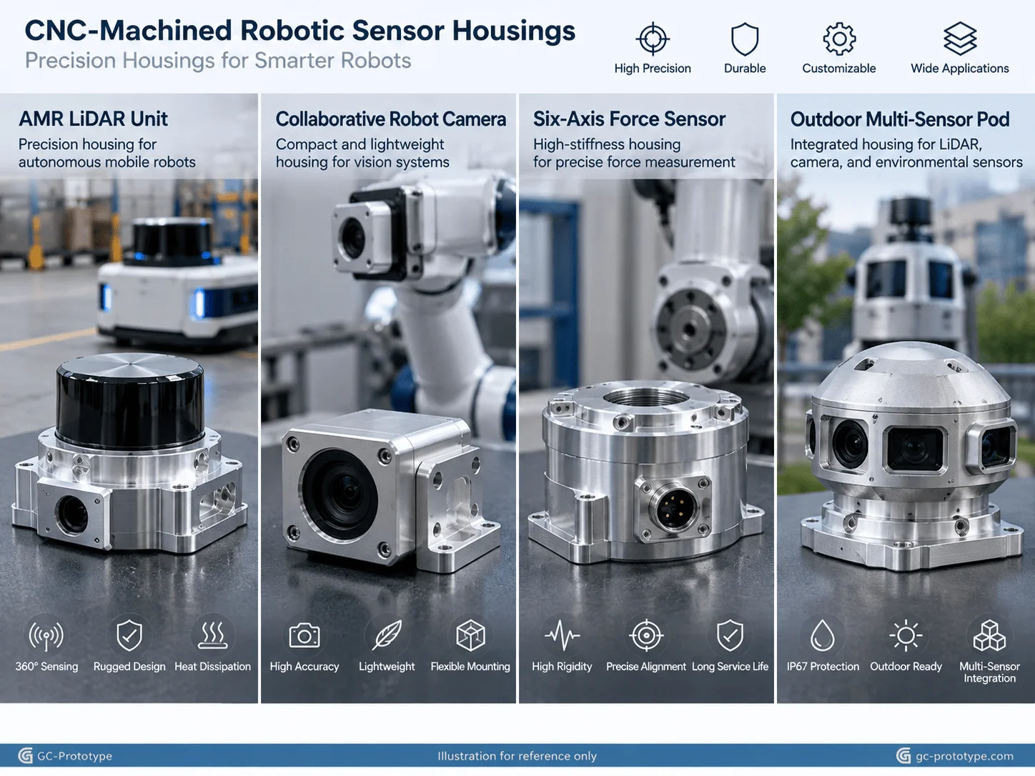
CNC machining tolerances for LiDAR sensor housings are becoming increasingly important as mobile robots, AMRs, collaborative robots, and intelligent automation systems rely on LiDAR, stereo cameras, IMUs, and force-torque sensors for real-time perception. For teams developing lightweight aluminum sensor enclosures for robotics, the enclosure must do far more than protect electronics—it must preserve optical alignment, manage heat, maintain EMI/RFI shielding continuity, and support reliable environmental sealing during functional testing.
When polymer prototypes cannot provide sufficient rigidity, conductive shielding, thread strength, or sealing stability, precision CNC machining gives Robotics Engineers, Senior Mechanical Engineers, Hardware Engineers, and Sourcing Managers a more representative path from CAD to real-world validation.
GC Prototype supports the complete development journey from CAD → prototype samples → functional validation → low-volume pilot production → production support, helping robotics companies verify sensor housings before committing to later-stage manufacturing.
Modern robots depend on increasingly sophisticated sensing systems.
Typical devices include:
LiDAR modules
Stereo vision cameras
Depth cameras
IMUs
Six-axis force-torque sensors
Ultrasonic sensors
Thermal cameras
Radar modules
These components effectively function as the robot’s eyes, balance system, and environmental awareness network.
The enclosure therefore has several simultaneous responsibilities:
Protect the sensor from vibration and impact
Maintain optical or mechanical alignment
Transfer heat away from electronics
Prevent water and dust ingress
Provide stable mounting datums
Protect cables and connectors
Support electrical grounding
Reduce electromagnetic interference
A housing that looks correct externally can still fail functional testing if the internal mounting surfaces are inaccurate.
For example, a small angular error in a LiDAR mounting interface can affect the sensor’s reference frame. A camera housing with poor flatness can introduce optical-axis misalignment. An incorrectly machined O-ring groove can create leakage even when the gasket material itself is suitable.
This is why sensor enclosure development should be treated as a precision mechanical engineering task rather than simple cosmetic packaging.
CNC machining is particularly valuable during NPI because it allows companies to manufacture housings directly from engineering metals without waiting for permanent tooling.
Design changes can be introduced quickly after:
Optical calibration
Environmental testing
Thermal testing
Robot vibration testing
Assembly evaluation
That flexibility reduces the cost of discovering a design problem late in the development cycle.
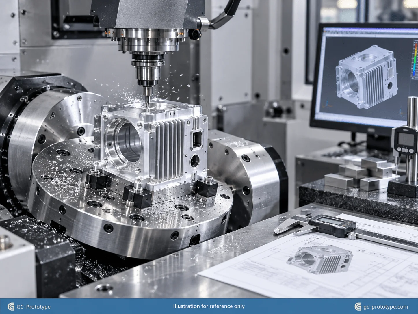
Lightweight aluminum sensor enclosures for robotics are widely used because aluminum combines low density, good thermal conductivity, CNC machinability, structural rigidity, and electrical conductivity.
For robotic vision and LiDAR systems, those characteristics solve several engineering problems at once.
A high-frame-rate camera or LiDAR processor may generate significant heat inside a compact package. At the same time, the robot designer wants to minimize weight because sensor modules are often mounted:
On the end of a robot arm
On a mobile robot mast
On an autonomous vehicle roof
Near a precision joint
Additional mass increases inertia and may reduce dynamic performance.
Two common alloys are 6061-T6 and 7075-T6.
| Engineering Factor | 6061-T6 | 7075-T6 |
|---|---|---|
| Strength | Good | Higher |
| Weight | Low | Low |
| Machinability | Excellent | Excellent |
| Thermal Conductivity | Better | Lower |
| Corrosion Resistance | Very good | More demanding |
| Cost | Lower | Higher |
| Typical Sensor Use | Camera/LiDAR housings | High-load lightweight structures |
6061-T6 offers a strong balance of manufacturing cost, corrosion resistance, thermal performance, and machinability.
It is well suited to:
LiDAR housings
Camera bodies
Electronics enclosures
Sensor mounting brackets
Thermal-management structures
For many prototypes, 6061-T6 provides enough stiffness while allowing thin-wall machining and integrated cooling fins.
7075-T6 becomes more attractive when structural strength and weight reduction are more important than thermal conductivity or material cost.
It may be selected for:
Highly loaded sensor brackets
End-of-arm sensor systems
Aerospace-style mobile robotics
Thin structural mounting frames
The correct material should follow the prototype’s actual test objective rather than a blanket preference for the strongest alloy.
A conductive aluminum enclosure can help form an effective electromagnetic shielding structure, but shielding performance depends on more than base material.
Engineers should also consider:
Electrical continuity between housing sections
Conductive gasket design
Connector bonding
Surface coatings
Fastener spacing
Grounding strategy
A decorative anodized surface is electrically insulating, so grounding points may require masking, conductive hardware, or a suitable conversion coating.
For electronics requiring reliable chassis conductivity, chromate conversion treatments may be considered where the project specification permits them.
The enclosure design should therefore coordinate:
Mechanical protection + thermal management + EMI strategy
rather than treating each requirement separately.
CNC machining can integrate heat-management geometry directly into the enclosure.
Common features include:
External cooling fins
Thermal contact pads
Internal heat-spreader surfaces
Airflow channels
Thin-wall structures
However, aggressive lightweighting can make the part difficult to machine.
Very thin walls may:
Vibrate during milling
Distort after unclamping
Lose flatness
Reduce sealing performance
A DFM review should therefore preserve adequate stiffness around:
Sensor mounting surfaces
Seal grooves
Connector interfaces
Threaded holes
while removing material from noncritical areas.
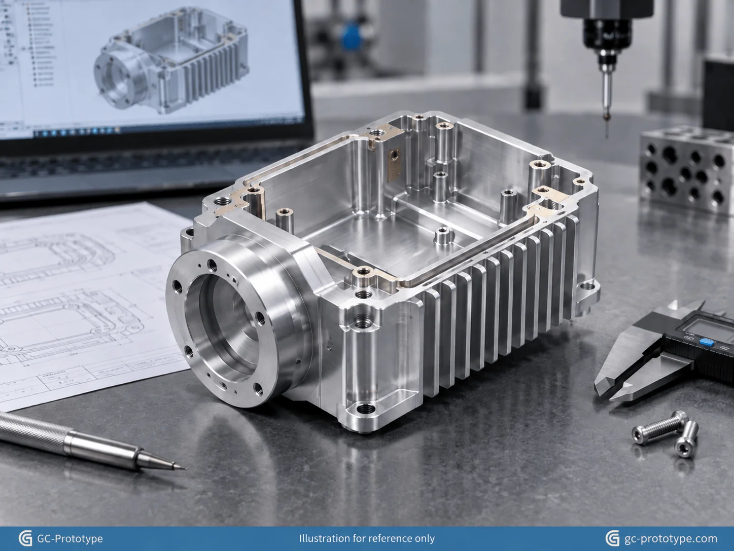
IP67 waterproof seal groove design cnc machining is critical when robot sensors must operate in outdoor, dusty, wet, or washdown-prone environments.
An IP67 rating is not created by the groove alone. It applies to the tested enclosure assembly under the relevant ingress-protection test conditions. Housing geometry, gasket selection, connector sealing, fasteners, assembly torque, surface finish, and manufacturing consistency all contribute to the result.
For prototype housings, CNC machining allows engineers to test the actual sealing concept before production tooling.
A typical seal system may include:
O-ring
Silicone gasket
Flat elastomer seal
The groove must control gasket compression without crushing or under-compressing the material.
Important variables include:
Seal cross-section
Groove width
Groove depth
Compression percentage
Corner geometry
Surface finish
Fastener spacing
There is no universal compression ratio suitable for every seal. The correct gland geometry should follow the gasket manufacturer’s design guidance and the actual pressure, temperature, material, and service environment.
The outline calls for approximately Ra 0.8 μm on critical sealing surfaces as a target for minimizing leakage risk.
A smooth sealing surface helps prevent:
Micro-leak paths
Local gasket damage
Uneven compression
However, roughness alone does not guarantee sealing.
Machining marks that cross a sealing path can become potential leakage channels. Toolpath strategy should therefore avoid pronounced steps or discontinuities along critical sealing surfaces.
Sharp internal corners are usually undesirable in machined seal grooves because standard end mills create radiused corners.
A well-designed groove should account for:
Cutter radius
Seal flexibility
Corner transitions
Using geometry that matches practical tooling improves consistency and reduces machining time.
An O-ring cannot compensate for a housing cover that deflects significantly between screws.
Fastener spacing should keep sealing pressure distributed around the perimeter.
This is particularly important for:
Large camera windows
Thin aluminum covers
Wide LiDAR housings
The enclosure should be evaluated as a complete mechanical system rather than a gasket groove in isolation.
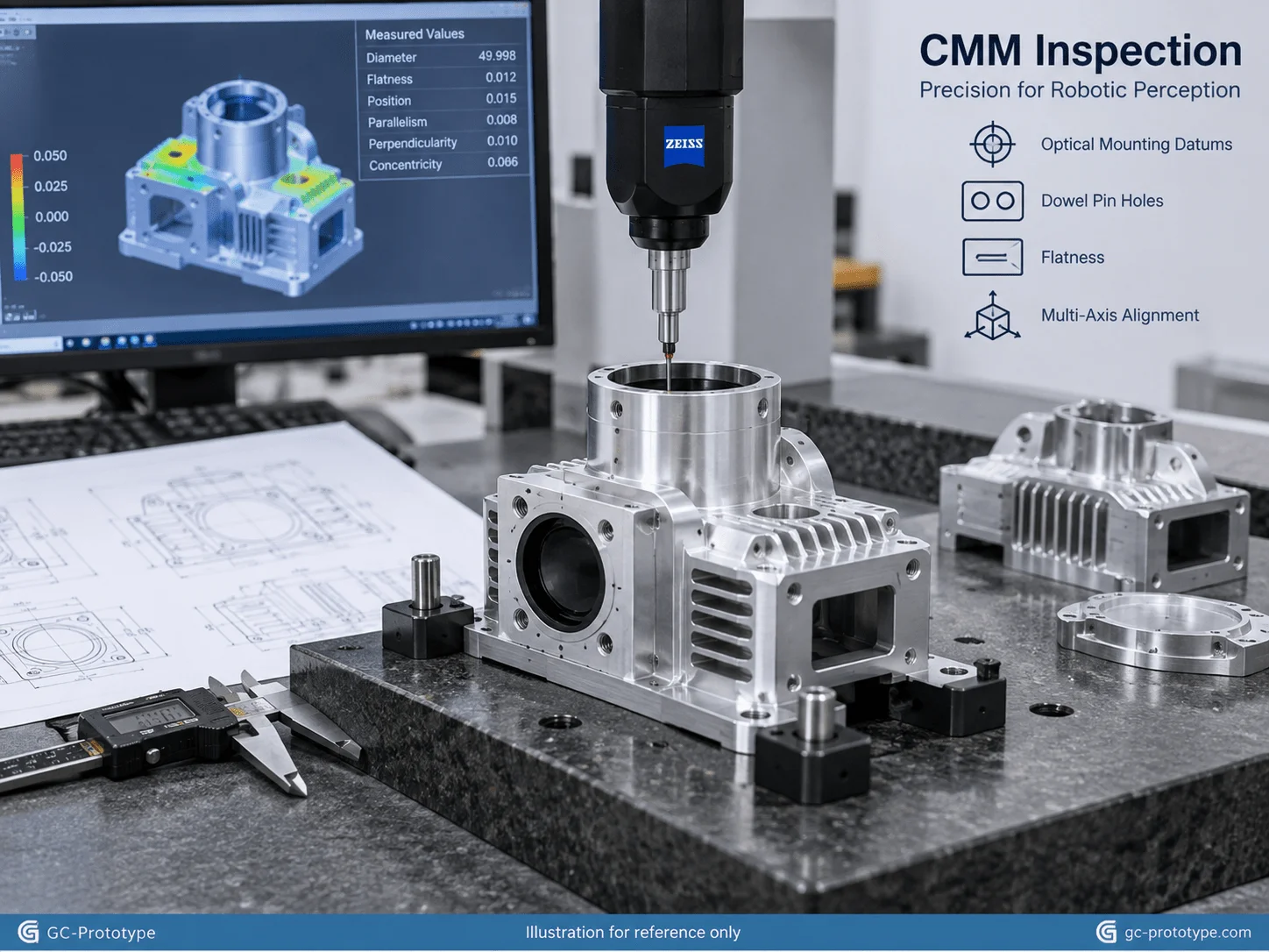
Achieving cnc machining tolerances for lidar sensor housings requires special attention to datums, flatness, hole position, and coaxial relationships.
Robotic sensing modules often include:
Optical assemblies
Lens mounts
Laser emitters and receivers
Camera sensors
Positioning pins
IMU reference surfaces
The sensor’s software may compensate for some calibration error, but mechanical stability remains essential.
The outline identifies flatness below 0.01 mm as a demanding target for selected critical mounting surfaces.
Such requirements should be applied only where they are functionally justified.
A practical tolerance hierarchy may look like this:
| Feature | Typical Priority |
|---|---|
| LiDAR reference mounting surface | Critical |
| Camera lens/interface datum | Critical |
| Dowel-pin holes | Critical |
| IMU mounting pad | High |
| Connector opening | General |
| Exterior cosmetic wall | General |
Applying ±0.01 mm-level precision to every external surface would add machining and inspection cost without improving sensor performance.
Dowel pins are useful when a sensor must be:
Removed
Serviced
Reinstalled
Recalibrated
Precision locating holes allow the assembly to return close to the original mechanical reference position.
Bolt clearance holes should generally provide clamping, while locating features should establish position.
Using screws themselves as precision locators may create inconsistent assembly alignment.
When several sensor mounting surfaces are positioned on different sides of an enclosure, multiple setups can introduce accumulated datum error.
Five-axis machining can reduce re-clamping by machining several critical surfaces in a single setup.
Advantages include:
Improved feature-to-feature position
Better angular consistency
Reduced datum transfer
Lower inspection complexity
This is especially valuable for sensor fusion assemblies where LiDAR, cameras, and IMUs must maintain accurate relationships.
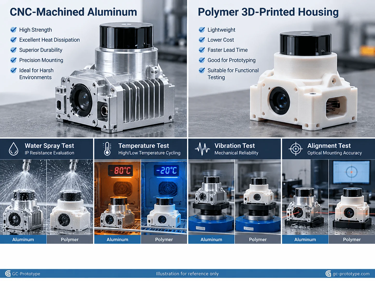
Comparing rapid cnc prototyping vs 3d printing for sensor cases should begin with the purpose of the test.
Both methods are valuable.
3D printing is excellent for:
Early geometry validation
Cable routing
Packaging
Visual design
Ergonomic studies
CNC machining becomes more valuable when the prototype must represent real enclosure behavior.
| Test Requirement | CNC Aluminum Housing | Typical Polymer 3D Print |
|---|---|---|
| Fit Check | Excellent | Excellent |
| Fast Early Iteration | Good | Excellent |
| EMI Shielding | Strong potential | Limited without coatings |
| Thermal Dissipation | Representative | Much lower |
| Thread Strength | Strong | Process-dependent |
| IP Seal Testing | Highly suitable | Surface/porosity dependent |
| High Vibration Testing | Strong | Material-dependent |
| Tight Datum Control | Excellent | Usually lower |
The outline proposes environmental validation including approximately -40°C to +85°C cycling, rain exposure, vibration, and drop testing for suitable projects.
These conditions should be treated as project-specific validation ranges rather than universal requirements.
During thermal cycling, different materials expand and contract differently.
A machined aluminum enclosure provides realistic information about:
Thermal expansion
Seal compression
Thread behavior
Optical datum stability
Robot sensor housings may experience shocks from:
Curb crossings
Arm collisions
Emergency stops
Vehicle vibration
CNC aluminum prototypes provide realistic rigidity and fastener behavior during these tests.
A plastic print can still be useful early in development, but its deformation may not represent the intended metal enclosure.
For 1–20 sensor housings, cost should be evaluated according to the information the prototype needs to deliver.
Major cost contributors include:
Aluminum stock
Number of setups
Deep cavities
Thin-wall machining
Tight datums
O-ring grooves
CMM inspection
Surface treatment
| Development Stage | Preferred Method | Reason |
|---|---|---|
| Early packaging concept | 3D printing | Low cost, fast revision |
| Optical mounting validation | CNC machining | Better datum control |
| IP sealing test | CNC machining | More representative surfaces |
| EMI/thermal test | CNC aluminum | Conductive and thermally realistic |
| Final functional validation | CNC machining | Closest to production-intent mechanics |
A printed housing may cost less initially, but if it cannot answer the relevant thermal, sealing, or alignment question, the lower purchase price may not reduce total development cost.
Engineering teams should evaluate:
prototype price + testing value + redesign risk
rather than piece price alone.
A sensor housing designed around CNC manufacturing can often be machined faster and at lower cost without sacrificing function.
Small internal radii require small tools.
Small cutters:
Remove material more slowly
Increase machining time
Are more prone to deflection
Where packaging allows, use larger internal radii that match standard tooling.
Deep electronics cavities may require long-reach tools.
This increases:
Chatter risk
Cycle time
Tool deflection
A stepped cavity or two-piece enclosure may sometimes be more economical.
Critical datums may deserve demanding flatness or position requirements.
Exterior cosmetic surfaces usually do not.
Separate:
Optical interfaces
Seal surfaces
Locating holes
from noncritical geometry on the drawing.
If the enclosure needs conductive grounding paths, surface finish should be considered before machining.
Chromate conversion coatings can maintain electrical conductivity while providing corrosion protection for suitable projects.
If anodizing is used elsewhere, mask:
Grounding pads
Connector bonding areas
Electrical contact surfaces
as required.
Sensor prototypes are frequently opened during NPI.
Thread inserts can improve durability where:
Covers are repeatedly removed
Sensors are frequently exchanged
High clamp load is required
This is particularly useful in softer aluminum threads subjected to repeated maintenance.
Make critical datums accessible to:
CMM probes
Surface plates
Gauges
A theoretically precise feature that cannot be measured conveniently creates unnecessary quality-control difficulty.
An AMR development team needs a lightweight enclosure for a roof-mounted LiDAR unit.
The CNC prototype includes:
Precision sensor datum
O-ring groove
Cable gland interface
Cooling fins
Testing evaluates:
IP sealing
Vibration
Optical stability
Thermal performance
A cobot wrist-mounted camera requires low weight and rigid alignment.
6061-T6 aluminum provides:
Lightweight structure
Heat dissipation
Robust threads
Conductive enclosure potential
Five-axis machining maintains the relationship between the camera mount and robot interface.
A force-torque sensing module requires precise mechanical reference surfaces.
CNC machining supports:
Flat mounting interfaces
Dowel locations
Cable routing
Protective covers
An agricultural or inspection robot requires a multi-sensor enclosure containing:
Cameras
IMU
LiDAR
Communication electronics
The prototype is machined for real environmental testing before tooling decisions are made.
A factory vision system needs precise camera-to-light alignment.
A CNC housing provides stable datums and heat management for long-duration functional validation.
A robust sensor enclosure program should evolve with the product.
The first stage evaluates:
Sensor packaging
Material
Seal geometry
Thermal design
EMI strategy
Machining access
Tolerances
The first physical housings verify:
Mechanical fit
Connector access
Optical alignment
Assembly sequence
Functional prototypes are then used for:
Thermal testing
Vibration
Ingress testing
Optical calibration
Drop testing
After the geometry stabilizes, pilot quantities can validate:
Process repeatability
Inspection planning
Assembly time
Surface treatment consistency
As volume increases, the manufacturing strategy may remain CNC-based or transition to:
Die casting
Extrusion plus CNC
Sheet metal
Injection molding for nonmetallic covers
GC Prototype supports the complete pathway from CAD → prototype samples → functional validation → low-volume pilot production → production support, allowing engineering and sourcing teams to maintain manufacturing continuity as designs mature.
CNC machining provides rigid metal structures, accurate mounting datums, strong threads, thermal conductivity, and conductive enclosure options for functional testing.
6061-T6 is usually the better general-purpose choice because of its thermal conductivity, corrosion resistance, machinability, and cost. 7075-T6 is useful when higher structural strength is required.
CNC machining can create accurate seal surfaces and O-ring grooves, but IP67 applies to the tested complete enclosure. Gaskets, connectors, fasteners, assembly, and verification testing are all part of the result.
The correct requirement depends on the seal system. For demanding prototype designs, a smooth surface such as approximately Ra 0.8 μm may be specified, but gasket supplier recommendations and actual test conditions should govern the final specification.
Mechanical datum errors can change sensor orientation relative to the robot coordinate system. Accurate flatness, position, and locating features improve repeatable alignment.
Yes. Machining several critical surfaces in fewer setups can reduce accumulated datum-transfer error between different sides of an enclosure.
Yes, especially for early geometry and packaging validation. CNC aluminum is usually more representative for EMI, thermal, sealing, high-vibration, and precision-datum testing.
Use practical corner radii, avoid unnecessarily deep cavities, apply tight tolerances selectively, design around standard tooling, and plan finishing and grounding requirements before machining.
They can be useful when covers or sensor modules will be repeatedly removed during development, especially where aluminum threads would otherwise see frequent assembly cycles.
Provide:
3D CAD/STEP files
2D drawings
Material
Quantity
Critical datums and GD&T
Seal requirements
Surface treatment
Environmental test requirements
Inspection expectations
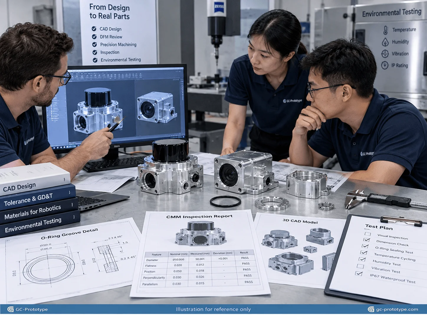
Robotic perception systems depend on mechanical stability as much as electronic performance.
A LiDAR unit cannot maintain reliable alignment if its mounting reference moves. A camera cannot perform consistently if the housing distorts under heat. An outdoor sensor pod cannot survive real-world deployment if its sealing surfaces or fasteners are poorly designed.
Precision CNC machining allows engineers to validate these mechanical requirements using production-intent metals before committing to later manufacturing processes.
By selecting appropriate lightweight aluminum sensor enclosures for robotics, engineering reliable ip67 waterproof seal groove design cnc machining, controlling cnc machining tolerances for lidar sensor housings, and evaluating rapid cnc prototyping vs 3d printing for sensor cases according to the real test objective, development teams can reduce uncertainty and accelerate product readiness.
The most effective enclosure is not the one with the tightest tolerance on every dimension. It is the one that applies precision exactly where optical alignment, sealing, heat transfer, grounding, and assembly require it.
GC Prototype supports robotics customers from CAD and prototype samples through functional validation, low-volume pilot production, and production support, helping bridge the gap between early engineering concepts and scalable manufacturing.
Protecting your mission-critical vision and LiDAR modules demands exact dimensional alignment and reliable IP-rated enclosure engineering. Whether you are a Senior Mechanical Engineer optimizing complex internal O-ring seal grooves or a Sourcing Manager evaluating rapid CNC prototyping vs 3D printing for sensor cases, GC Prototype provides precision manufacturing support from prototype to production.