Address:
Shenzhen Bao'an District Xinqiao Subdistrict Huangpu Community Huangpu East Ring Road No. 504 Shenzhen Yuan Industrial City Building C
Work Hours:
Monday to Friday: 9AM - 21PM
Weekend: 9AM - 21PM

Address:
Shenzhen Bao'an District Xinqiao Subdistrict Huangpu Community Huangpu East Ring Road No. 504 Shenzhen Yuan Industrial City Building C
Work Hours:
Monday to Friday: 9AM - 21PM
Weekend: 9AM - 21PM

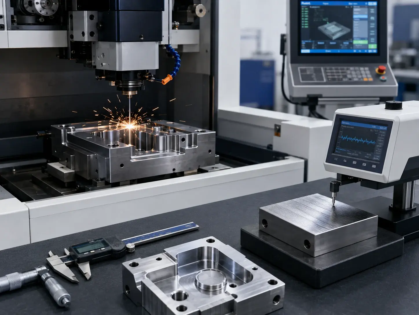
Electrical discharge machining EDM surface finish control becomes essential when hardened steel, carbide, deep cavities, narrow slots, sharp internal details, or micro-scale features cannot be produced reliably with conventional cutting tools. Instead of applying mechanical cutting force, EDM removes conductive material through controlled electrical discharges between an electrode and the workpiece. This makes it valuable for injection molds, aerospace components, medical instruments, semiconductor tooling, robotics parts, and precision industrial equipment.
For Senior Mechanical Engineers, Industrial Designers, Manufacturing Managers, and Sourcing Professionals, the main challenge is not simply deciding whether EDM can make the geometry. The more important questions are what surface texture is required, how that finish affects fatigue and molding performance, which tolerances are realistic, and how much finishing time is economically justified.
This guide explains VDI texture grades, wire EDM roughness, mirror finishing, white-layer control, micro EDM applications, DFM limitations, cost reduction, and supplier qualification for demanding B2B projects.
How EDM Creates a Surface
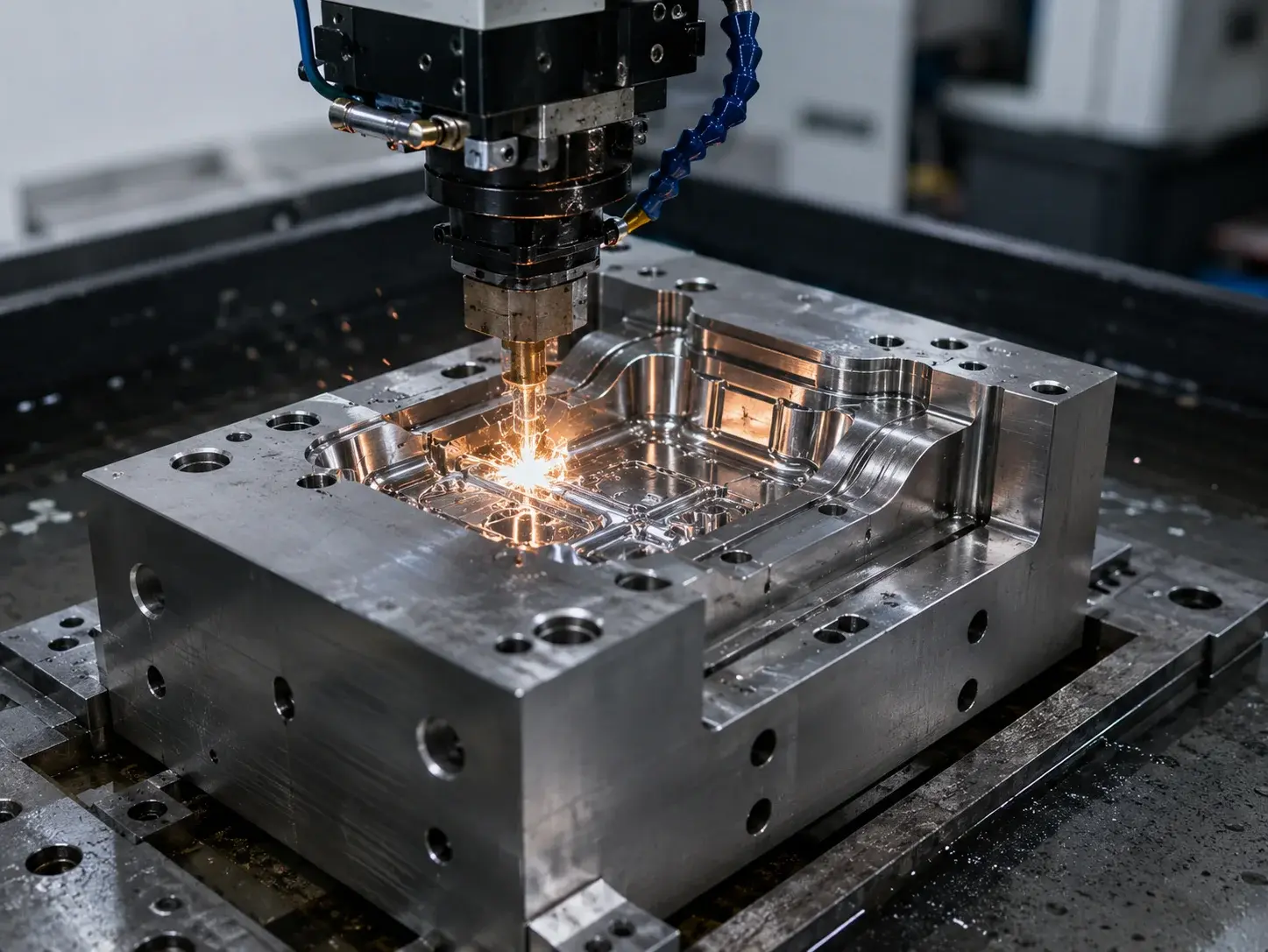
EDM is a thermal, non-contact machining process. A shaped electrode or continuously moving wire is separated from the conductive workpiece by a small gap filled with dielectric fluid. Repeated electrical discharges generate localized heat, melting and vaporizing microscopic amounts of material. The dielectric then cools the zone and helps flush debris away.
Two processes dominate industrial use:
Sinker EDM uses a graphite, copper, or copper-tungsten electrode to reproduce cavities, ribs, slots, logos, textures, and internal forms.
Wire EDM uses a thin moving wire to cut through conductive material, making precision profiles, punches, dies, gears, and narrow slots.
Because the tool does not physically push against the workpiece, EDM can machine hardened materials and fragile features with low cutting force. Wire EDM can also leave smooth, burr-free surfaces when the machine, wire, dielectric, and cutting strategy are properly controlled.
| Process | Best suited to | Main surface consideration |
| Sinker EDM | Blind cavities, deep ribs, mold details | Electrode texture, orbiting, flushing |
| Wire EDM | Through-profiles and precision contours | Number of skim cuts, wire type, dielectric |
| Micro EDM | Micro-holes and miniature features | Electrode wear and debris evacuation |
| Mirror EDM | Fine mold cavities and optical-quality tooling | Long finishing cycles and process stability |
Texture Standards and Aesthetics
Demystifying the vdi 3400 texture standard chart
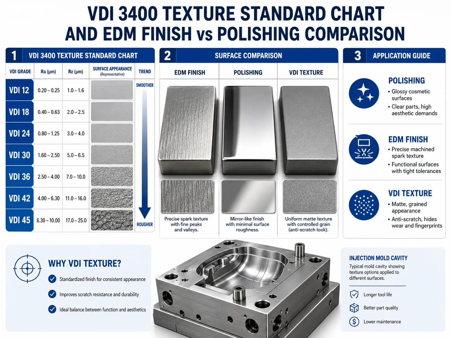
The vdi 3400 texture standard chart gives moldmakers and product designers a practical language for specifying spark-eroded textures. Commonly referenced grades run from VDI 12 through VDI 45, with lower numbers representing finer matte surfaces and higher numbers representing progressively coarser textures. The most widely used commercial charts associate these grades with approximate Ra values, although the final appearance must be approved using a physical plaque or molded sample rather than a number alone.
| VDI grade | Approximate Ra | Typical visual effect | Example application |
| VDI 12 | 0.40 μm | Fine satin | Premium electronics details |
| VDI 15 | 0.56 μm | Fine matte | Small housings and buttons |
| VDI 18 | 0.80 μm | Soft matte | Medical and laboratory enclosures |
| VDI 21 | 1.12 μm | General matte | Consumer product housings |
| VDI 24 | 1.60 μm | Medium texture | Industrial controls |
| VDI 27 | 2.24 μm | Noticeable grain | Tool and equipment grips |
| VDI 30 | 3.15 μm | Coarse matte | Automotive interior components |
| VDI 33 | 4.50 μm | Coarse texture | Durable industrial covers |
| VDI 36 | 6.30 μm | Rough grain | Anti-slip surfaces |
| VDI 39 | 9.00 μm | Heavy texture | Rugged outdoor equipment |
| VDI 42 | 12.50 μm | Very heavy grain | Specialized functional texture |
| VDI 45 | 18.00 μm | Extremely coarse | Strong anti-slip applications |
A VDI specification should include more than the grade. The drawing should identify the exact textured surface, polymer, color, gloss expectation, draft angle, and acceptable variation. Texture appearance can change with resin type, pigment, mold temperature, filling direction, and wall thickness.
Coarser textures generally require more draft because the molded plastic must release from the microscopic peaks and valleys of the cavity. A texture that looks attractive on a flat sample can create drag marks or ejection damage on a deep vertical wall with insufficient draft.
For consumer electronics and smart hardware, fine grades can reduce glare and create a controlled tactile feel, while coarser grades improve grip. A physical texture plaque remains the safest approval method because Ra values alone cannot communicate gloss or tactile response.
Tooling Options: edm finish vs polishing for injection molds
The choice between edm finish vs polishing for injection molds depends on the product’s visual target, release behavior, maintenance needs, and budget. Leaving a controlled EDM texture can be intentional rather than unfinished workmanship.
A fine spark finish creates an even matte appearance and can disguise minor weld lines, sink-related gloss differences, and small surface inconsistencies. It is also useful in recesses where manual polishing is difficult. By contrast, polishing removes the EDM texture and progressively creates a smoother satin, gloss, or mirror surface.
| Decision factor | Controlled EDM finish | Polished finish |
| Appearance | Matte or textured | Satin to mirror gloss |
| Labor | Lower when finish is achieved in-machine | High for manual fine polishing |
| Defect visibility | Can hide minor visual variation | Highlights flow and sink variation |
| Release behavior | Requires adequate draft | Smooth surfaces may release more easily |
| Maintenance | Texture must remain consistent after repair | Polished areas can be reworked locally |
| Best use | Housings, grips, industrial surfaces | Clear parts, lenses, premium gloss surfaces |
Mirror polishing is normally reserved for transparent optical parts and high-gloss cosmetic panels. Product designers should define Class-A surfaces and avoid expensive polishing on hidden ribs, slots, or inaccessible corners.
Engineering Precision and Quality Control
Achieving Optimal wire edm surface roughness values
Target wire edm surface roughness values are achieved through a sequence of rough cutting and progressively lower-energy skim cuts. A rough cut removes material quickly but leaves a more pronounced crater pattern and a larger thermally affected zone. Each skim pass corrects geometry and refines the surface.
Actual results depend on the machine, workpiece thickness, alloy, wire diameter, wire coating, dielectric, flushing conditions, and programmed technology. Modern high-end systems can achieve submicron Ra finishes in appropriate conditions; Sodick publishes examples around 0.36 μm Ra on stainless steel and as fine as 0.05 μm Ra on carbide using oil dielectric. These are application-specific machine demonstrations, not universal guarantees.
| Cutting strategy | Indicative finish range | Typical purpose |
| One rough cut | Ra 2.0–4.0 μm | Fast blank separation |
| Rough cut + one skim | Ra 1.0–2.0 μm | General tool components |
| Rough cut + two skims | Ra 0.5–1.0 μm | Precision profiles |
| Multiple fine skims | Ra 0.2–0.5 μm | High-accuracy dies and aerospace parts |
| Specialized fine-finish setup | Below Ra 0.2 μm | Selected micro and mirror applications |
These ranges should be treated as quotation-stage guidance. The supplier should confirm the achievable finish on the specified material and thickness.
Surface roughness is only one requirement. Taper, straightness, corner accuracy, recast layer, and dimensional stability may be more important. Internal corner radii are limited by wire diameter and discharge gap. Drawings should also identify the required roughness parameter and measurement location because Ra, Rz, and visual appearance are not interchangeable.
The Critical Factor: edm white layer thickness control
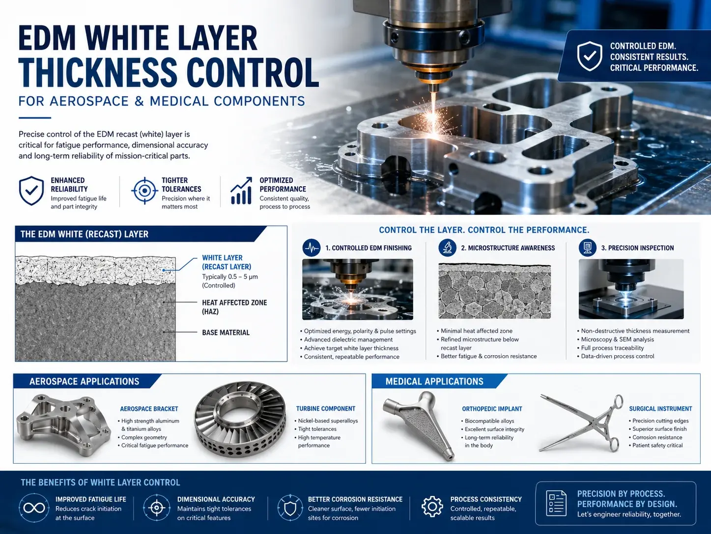
Effective edm white layer thickness control protects surface integrity in fatigue-sensitive, corrosion-sensitive, or highly loaded components. During EDM, some molten material is expelled, while a small amount can rapidly resolidify on the surface. This recast region is commonly called the white layer because of its appearance under metallographic examination.
The layer may contain altered microstructure, tensile residual stress, microcracks, and material transferred from the electrode or dielectric. Research on EDM surface integrity shows that thermal gradients and recast layers can reduce fatigue performance or corrosion resistance under certain conditions.
White-layer thickness is influenced by pulse energy, pulse duration, material, flushing, electrode condition, and finishing strategy. High-energy roughing generally produces faster removal but a rougher surface and more thermal alteration. Low-energy finishing passes reduce the affected layer.
For injection molds, a controlled recast layer may be acceptable if the target is a stable spark texture and no cracking is present. For aerospace splines, medical tools, stamping punches, pressure components, and cyclically loaded parts, the engineering team may require additional control.
Possible controls include:
Multiple low-energy finishing passes
Improved flushing and debris removal
Stable dielectric temperature and cleanliness
Reduced pulse duration during final passes
Light grinding, polishing, honing, or lapping
Metallographic verification on qualification samples
Surface roughness and microcrack inspection
The drawing should not demand “zero white layer” without a defined inspection method. A useful specification identifies the maximum allowable layer, sampling plan, measurement method, and whether isolated microcracks are permitted.
High-Tech Applications: micro edm surface treatment advantages
The main micro edm surface treatment advantages are the ability to create miniature conductive features with low mechanical cutting force and minimal conventional burr formation. Micro EDM is used for tiny holes, narrow slots, micro-cavities, miniature gears, precision nozzles, and delicate tooling features.
Applications include medical instrument jaws, microfluidic tooling, semiconductor fixtures, miniature robotics mechanisms, and precision sensors. The process can machine hard materials without deflecting a fragile cutting tool, but electrode wear, difficult flushing, and specialized inspection can increase cost.
Cost and DFM Optimization
Technical Strategies: how to reduce edm machining costs
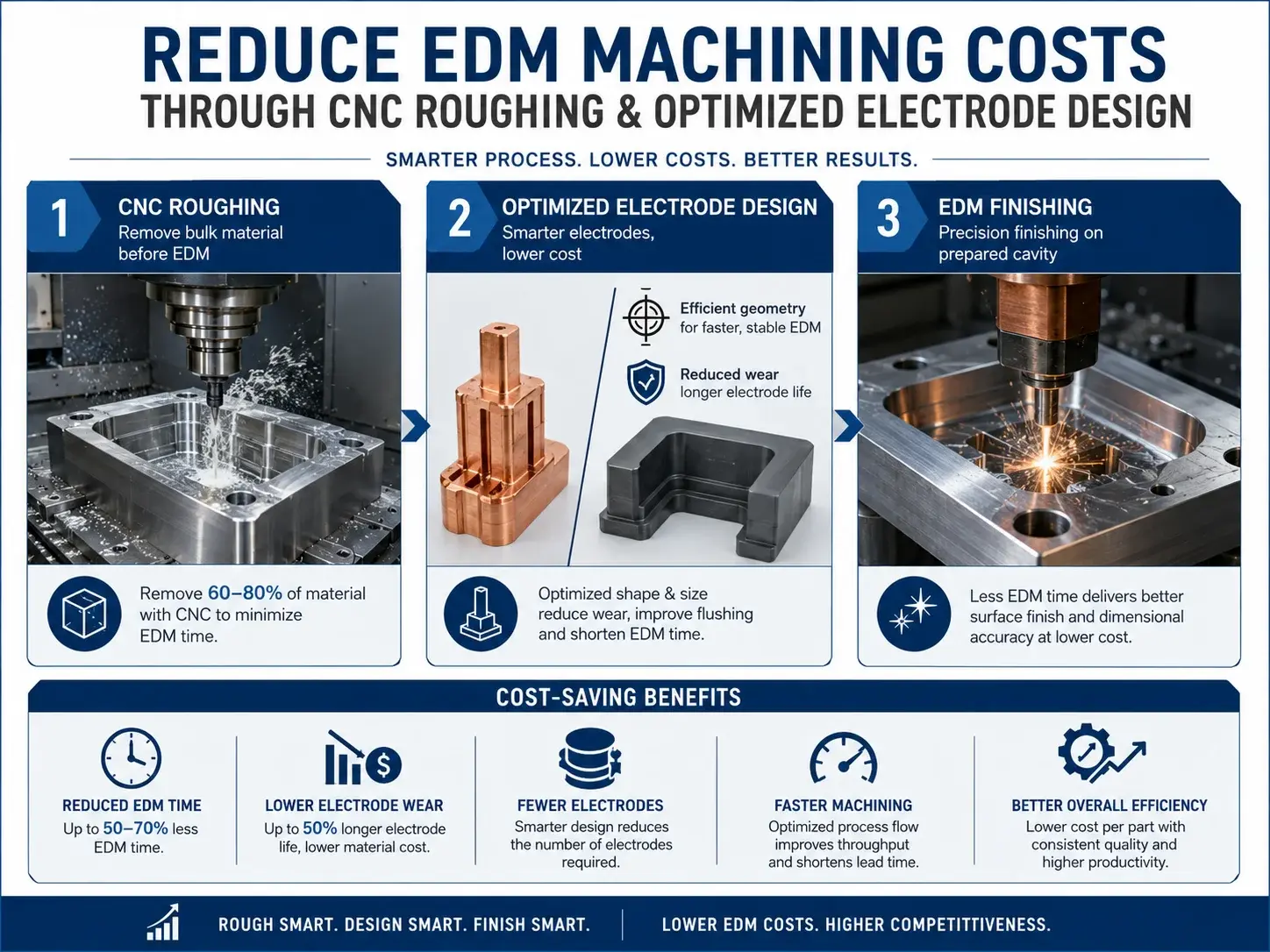
Knowing how to reduce edm machining costs starts with understanding that machine time, electrode production, electrode wear, and inspection drive the quotation. EDM is most economical when it is reserved for geometry that conventional machining cannot produce efficiently.
The first strategy is to remove bulk material by CNC milling, turning, drilling, or grinding before EDM. Using sinker EDM to remove a large open volume wastes machine time and electrode life. CNC roughing should leave only the material required for the final inaccessible geometry.
The second strategy is to simplify deep, narrow ribs and slots. Such features may require long fragile electrodes, multiple roughing and finishing electrodes, slow flushing, and conservative parameters. Increasing slot width, reducing depth, or adding access can lower cost substantially.
Additional cost controls include:
Specify fine finishes only on functional or visible surfaces.
Use standard electrode materials and practical electrode shapes.
Avoid unnecessarily tiny internal corner radii.
Combine similar features into reusable electrode strategies.
Provide clear datums and inspection priorities.
Allow practical overcut and taper limits.
Group parts to reduce setup and programming time.
Use wire EDM for through-features instead of sinker EDM where appropriate.
Avoid duplicate finishing operations when the EDM finish is acceptable.
| Cost driver | Why it increases price | Practical response |
| Deep narrow cavity | Poor flushing and slow removal | Pre-machine, widen, or reduce depth |
| Ultra-fine finish | Multiple low-energy passes | Limit to critical surfaces |
| Complex electrode | More design and machining time | Simplify geometry or segment logically |
| High electrode wear | Multiple replacement electrodes | Select suitable electrode material and parameters |
| Tight tolerance everywhere | Longer finishing and inspection | Apply tight limits only to critical features |
| Urgent delivery | More machine scheduling pressure | Release stable CAD and complete drawings early |
A useful RFQ should separate roughing, finishing, electrode manufacture, inspection, and post-processing. This allows the engineering and sourcing teams to see where design changes will create the greatest savings.
Navigating electrical discharge machining edm surface finish Challenges
Managing electrical discharge machining edm surface finish requirements involves balancing roughness, removal rate, electrode wear, dimensional accuracy, and surface integrity. Improving one variable can worsen another.
High-energy parameters remove material quickly but create larger craters. Low-energy parameters improve finish but increase cycle time. In deep cavities, poor flushing may cause unstable discharges, local burning, taper, and non-uniform texture. Large surface areas also require careful electrode orbiting and uniform dielectric flow.
DFM recommendations include:
Provide venting or flushing access for deep cavities.
Avoid abrupt changes from broad surfaces to very narrow gaps.
Define realistic internal corner radii.
Add stock for post-EDM grinding where surface integrity is critical.
Identify which surfaces require VDI texture and which can remain machined.
Keep electrodes rigid enough to resist thermal and handling distortion.
Consider electrode access when defining cavity orientation.
Review how the part will be measured after machining.
For mold cavities, the final plastic appearance is affected by both the steel texture and the molding process. An EDM supplier can certify steel roughness, but cannot alone guarantee final gloss on every polymer and molding condition.
Application Scenarios
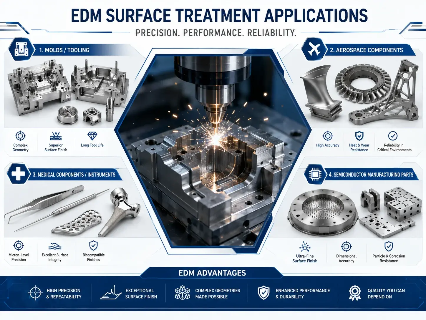
Injection Mold Texture
A consumer electronics team needs a consistent matte finish on an ABS housing. The mold cavity can be finished to an approved VDI grade, while the designer validates the result using molded texture plaques. Adequate draft is added to prevent drag marks.
Aerospace Spline and Seal Feature
An aerospace supplier requires a hardened-steel spline with tight profile accuracy and controlled surface integrity. Wire EDM roughing and skim cuts establish geometry, followed by verification of roughness, recast layer, and critical dimensions.
Medical and Semiconductor Micro-Features
Medical and semiconductor teams use micro EDM for narrow slots, micro-holes, and delicate conductive features. Optical inspection, electrode-wear compensation, and controlled flushing are essential at this scale.
Automotive Tooling Insert
A tooling manufacturer can CNC-machine accessible material first, then use sinker EDM for deep ribs and sharp internal details in hardened steel.
Sourcing Precision
Choosing a Partner for custom precision edm services
A supplier offering custom precision edm services should demonstrate process capability, surface measurement, electrode engineering, and quality control—not only machine availability.
For mold work, look for sinker EDM systems capable of stable fine finishing and controlled orbiting. For precision profiles, the supplier should have modern wire EDM equipment, appropriate wire options, dielectric management, and experience with multiple skim cuts. Mirror EDM capability is valuable when extremely fine mold surfaces are required.
The inspection system should match the project. A profilometer is required for quantified roughness, while CMM or optical measurement may be needed for geometry. A supplier qualification checklist should cover:
Experience with the specified alloy and hardness
Sinker, wire, micro, or mirror EDM capability
Graphite and copper electrode manufacturing
Wire diameter and fine-wire options
Roughness measurement capability
Temperature-controlled inspection
White-layer or metallographic support when required
Electrode wear compensation
DFM and cost-reduction feedback
Traceability and revision control
Secondary grinding, polishing, and heat treatment
First-article and inspection reporting
A complete quotation package should include 3D CAD, 2D drawings, material, hardness, quantity, critical tolerances, roughness parameters, VDI grades, white-layer limits, inspection method, and required certificates.
The supplier should identify electrode split lines, achievable corner radii, taper, measurement access, and secondary-finishing assumptions before machining begins.
Frequently Asked Questions
What materials can EDM machine?
EDM can machine electrically conductive materials, including hardened steels, carbide, titanium, aluminum, copper alloys, and many superalloys. Material hardness is less restrictive than in conventional cutting, although conductivity, thermal behavior, and electrode compatibility affect performance.
What is the difference between sinker EDM and wire EDM?
Sinker EDM uses a shaped electrode to create blind cavities and complex internal forms. Wire EDM uses a moving wire to cut through the workpiece and is best for precision through-profiles.
What does a VDI number mean?
A VDI number identifies an approximate spark-texture grade. Lower grades are finer, while higher grades are rougher. The final appearance should be approved with a physical reference sample.
Can EDM produce a mirror finish?
Specialized mirror EDM can produce extremely fine surfaces under controlled conditions. The achievable result depends on steel quality, machine technology, electrode, dielectric, cavity geometry, and finishing time. Manual polishing may still be required for optical surfaces.
How smooth can wire EDM cut?
General wire EDM work may range from several micrometers Ra after rough cutting to submicron finishes after multiple skim cuts. Selected machines and conditions can achieve much finer results, but the supplier must confirm capability for the actual material and thickness.
Does EDM leave burrs?
EDM does not create conventional cutting burrs because there is no shearing tool edge. It can still leave recast material, wire-entry marks, start-hole effects, or localized edge conditions that require review.
What is the EDM white layer?
The white layer is resolidified material created by the thermal EDM process. Its thickness and integrity depend on machining parameters, material, flushing, and finishing passes.
How can EDM costs be reduced?
Pre-machine bulk material, simplify deep narrow features, limit ultra-fine finishes to critical surfaces, use realistic radii and tolerances, and select wire EDM instead of sinker EDM for suitable through-features.
Is EDM suitable for medical parts?
Yes, especially for conductive miniature or hardened components. Surface integrity, cleaning, traceability, and validation requirements must be defined according to the medical application.
What information is needed for an EDM quote?
Provide 3D CAD, dimensioned drawings, material and hardness, quantity, tolerances, surface roughness, VDI texture, white-layer requirements, inspection standards, and delivery expectations.
EDM solves manufacturing problems that conventional tools cannot address efficiently. It can machine hardened conductive materials, deep mold cavities, narrow slots, precision contours, and micro-scale features while applying almost no mechanical cutting force.
Successful EDM design requires more than specifying a roughness number. Engineers must coordinate VDI texture, draft, wire passes, corner radii, flushing, electrode wear, white-layer control, measurement, and post-processing. Procurement teams must evaluate total process capability rather than comparing machine-hour rates alone.
Bring Your Precision EDM Project to Production
Achieving a flawless technical texture or micro-level tolerance on hardened steel requires a deep understanding of discharge physics. Whether you are a Senior Mechanical Engineer specifying aerospace splines or an Industrial Designer defining VDI textures for consumer electronics, GC-Prototype has the mirror EDM, sinker EDM, and wire EDM capabilities to bring your designs to life.
Our team supports electrode design, CNC pre-machining, precision EDM, VDI texture development, surface inspection, polishing, and low-volume manufacturing for global B2B projects.