Address:
Shenzhen Bao'an District Xinqiao Subdistrict Huangpu Community Huangpu East Ring Road No. 504 Shenzhen Yuan Industrial City Building C
Work Hours:
Monday to Friday: 9AM - 21PM
Weekend: 9AM - 21PM

Address:
Shenzhen Bao'an District Xinqiao Subdistrict Huangpu Community Huangpu East Ring Road No. 504 Shenzhen Yuan Industrial City Building C
Work Hours:
Monday to Friday: 9AM - 21PM
Weekend: 9AM - 21PM

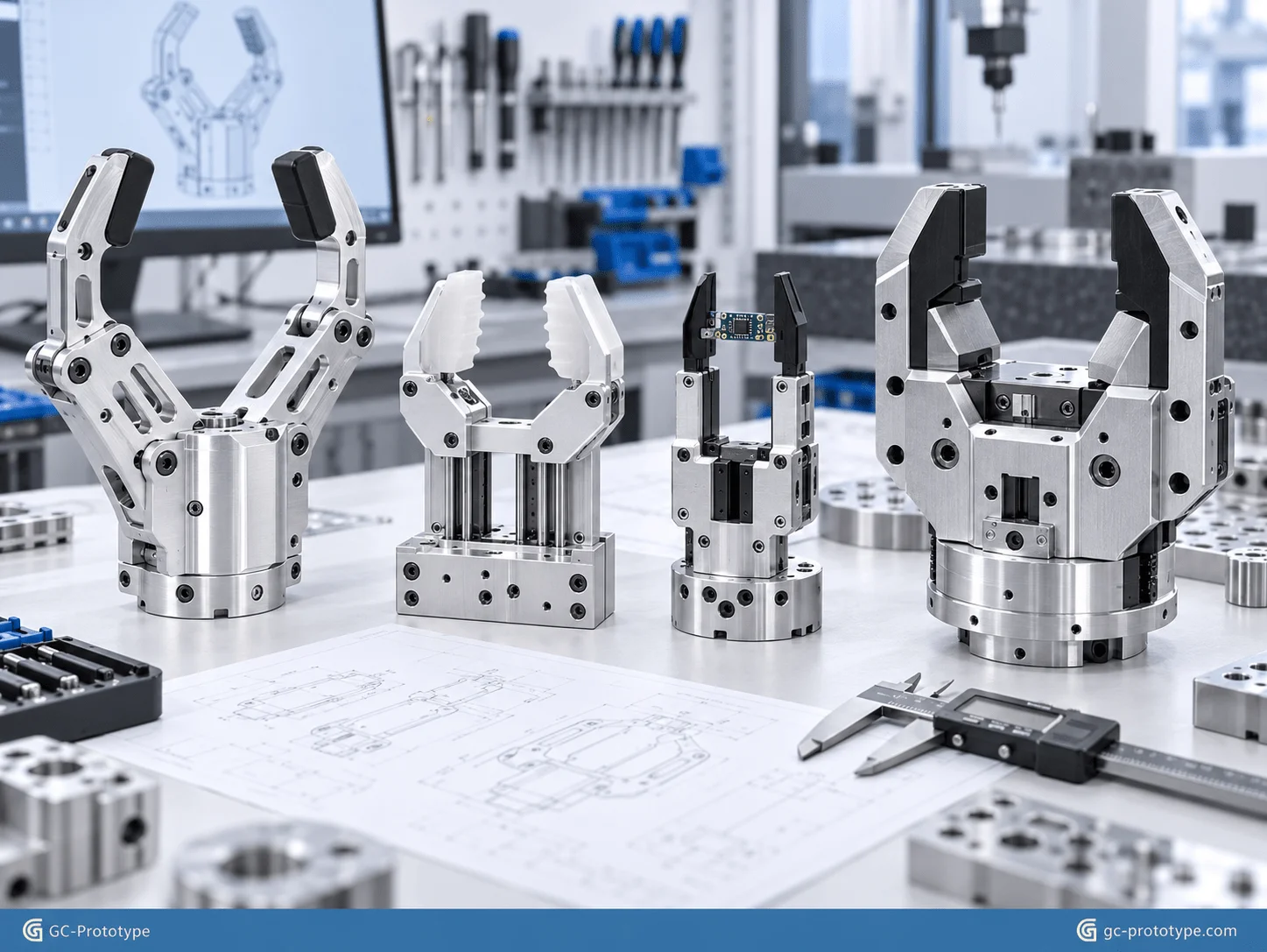
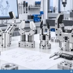
A CNC robotic gripper prototype must do more than look correct in CAD. Robotics teams exploring lightweight aluminum cnc machining for robot grippers or rapid prototyping robotic gripper fingers need functional parts that can survive real gripping loads, repeated opening and closing, sliding contact, fast acceleration, and precise sensor feedback. When polymer 3D-printed fingers begin to flex, wear, or lose alignment under demanding tests, custom CNC machining provides the stiffness, dimensional control, and durable threaded interfaces required for meaningful EOAT validation.
For Robotics Engineers, Senior Mechanical Engineers, NPI Engineers, and Sourcing Managers, gripper development usually involves four connected challenges: reducing end-of-arm inertia, producing custom finger geometry quickly, controlling precision sliding and dowel interfaces, and keeping prototype costs reasonable across several design iterations. This guide focuses specifically on prototype manufacturing and engineering validation, not mass-production supply.
Why CNC Machining Matters for Robotic Gripper Prototypes
A robotic gripper is one of the most mechanically demanding elements of an automation system because it directly interacts with the workpiece. Unlike a static bracket or enclosure, a gripper repeatedly accelerates, clamps, releases, slides, and absorbs reaction forces.
Prototype testing may need to evaluate:
Maximum gripping force
Finger deflection
Slider friction
Jaw parallelism
Dowel-pin repeatability
Fastener durability
Servo or pneumatic response
Impact resistance
Thermal behavior
Long-cycle wear
Sensor alignment
A basic polymer prototype may be perfectly suitable for early envelope checks, finger-spacing validation, or collision analysis. Once engineering moves toward functional testing, however, the material and mechanical interfaces become far more important.
CNC machining allows prototype grippers to be produced directly from engineering materials such as:
6061-T6 aluminum
7075-T6 aluminum
Stainless steel
Tool steel for selected contact parts
POM
PEEK
Other engineering plastics
For a gripper body, aluminum provides a useful combination of low weight, stiffness, machinability, and heat dissipation. Harder materials may be used selectively for wear inserts, pins, or contact components.
Another major advantage is tooling-free iteration. If an NPI team tests three finger profiles and discovers that one requires a revised contact angle, the CAD file can be updated and a new prototype machined without modifying a mold.
A typical gripper prototyping workflow may include:
1.CAD design and gripping-force analysis
2.DFM review
3.Material selection
4.CNC machining
5.Dimensional inspection
6.Surface treatment
7.Assembly with guides, bearings, sensors, and actuators
8.Dynamic gripping test
9.Wear and repeatability evaluation
10.CAD revision
This iterative workflow makes CNC machining particularly suitable for 1–10 prototype sets where the objective is learning rather than production volume.
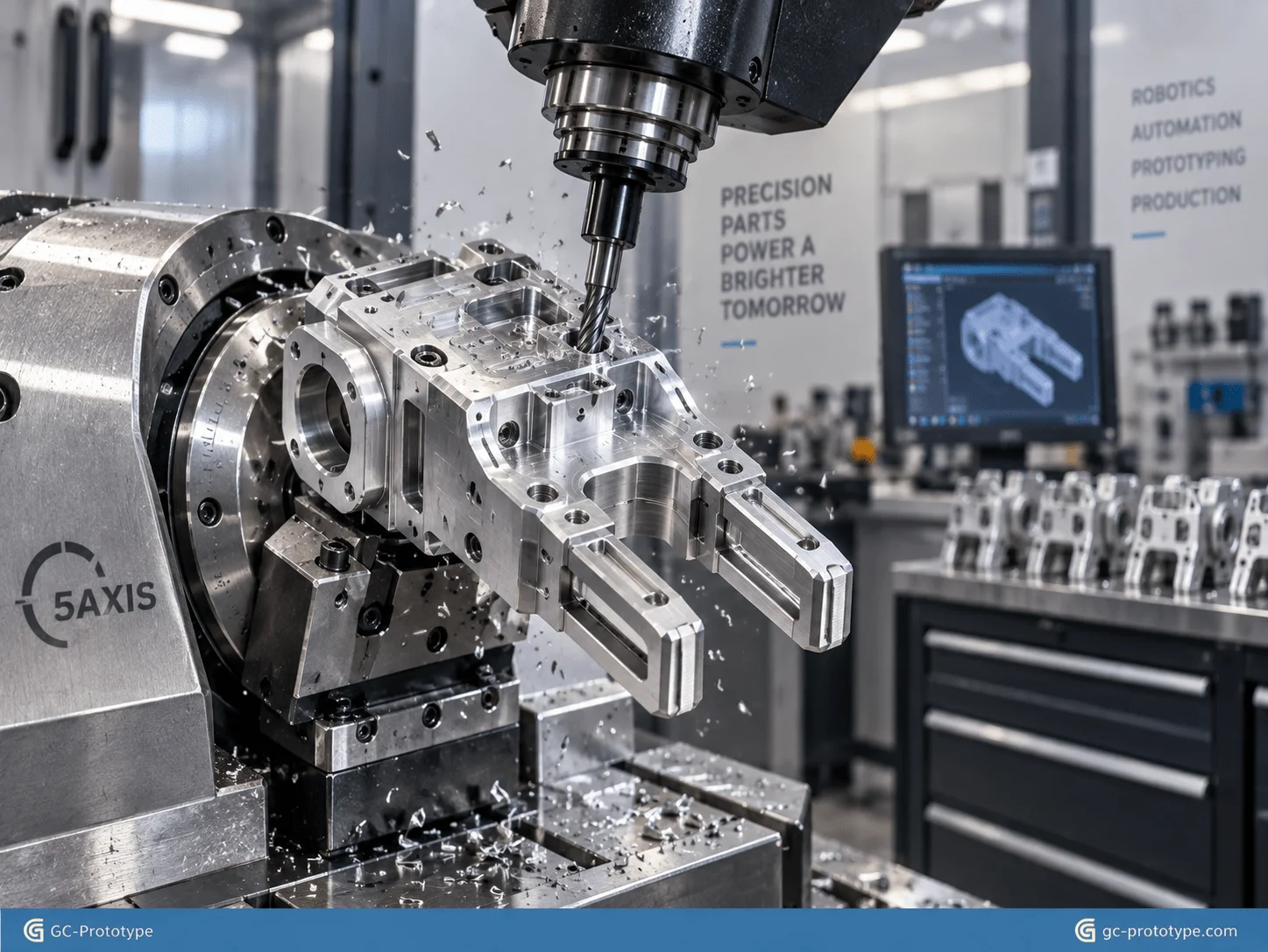
Structural Integrity & Material Selection
Minimizing Payload Inertia with lightweight aluminum cnc machining for robot grippers
Using lightweight aluminum cnc machining for robot grippers helps robotics engineers reduce end-of-arm mass while maintaining the stiffness required for reliable gripping.
Payload capacity is not determined only by the weight of the workpiece. The robot also carries the gripper, fingers, sensors, cables, adapters, and any additional tooling mounted at the wrist.
Every gram added to the end effector increases the moving mass that the robot must accelerate and decelerate.
A lighter gripper may help improve:
Servo response
Acceleration capability
Cycle time
Motion stability
Available payload margin
Energy efficiency
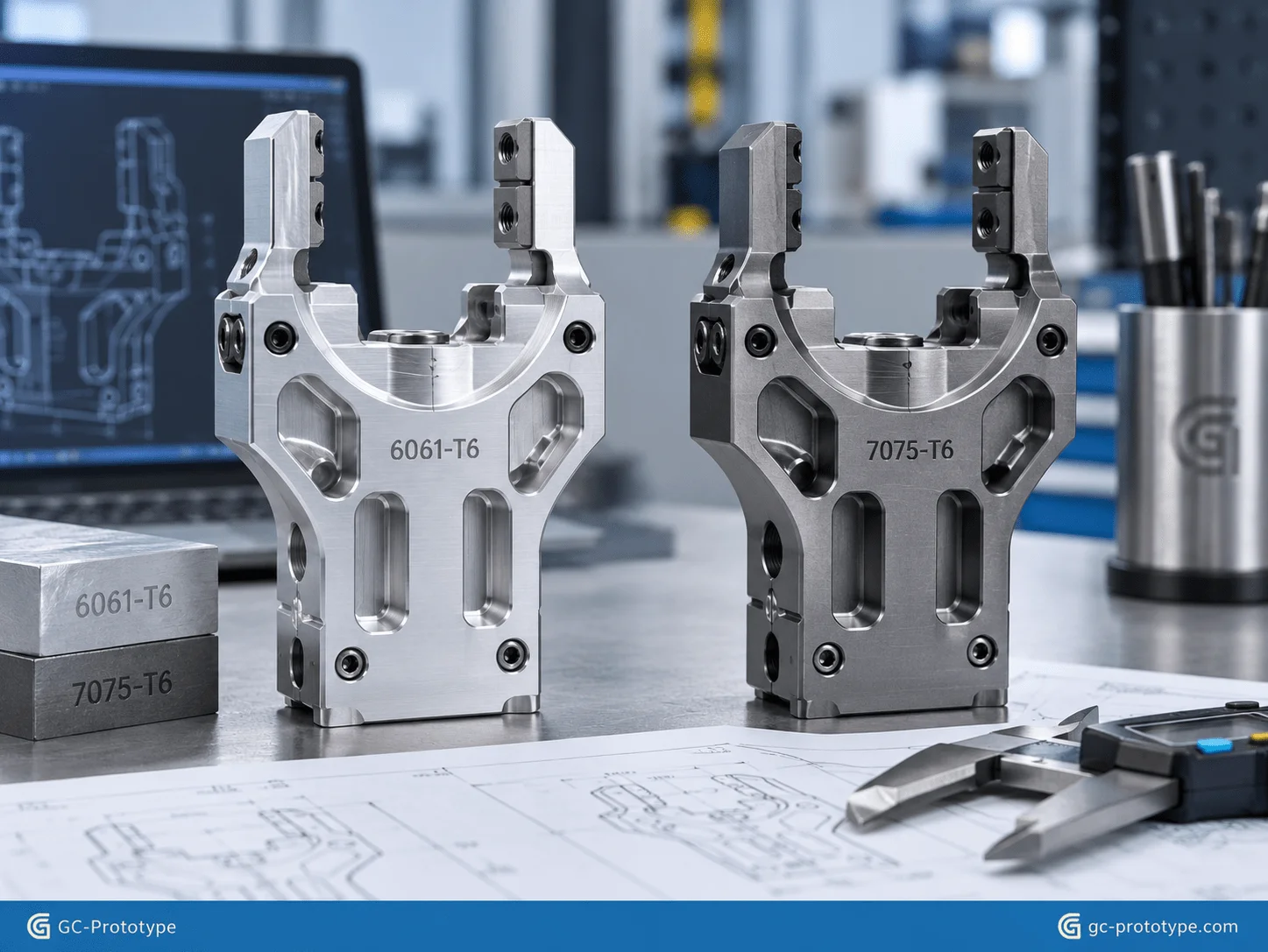
Two frequently evaluated materials are 6061-T6 and 7075-T6 aluminum.
| Engineering Factor | 6061-T6 | 7075-T6 |
|---|---|---|
| Strength | Good | Higher |
| Weight | Low | Low |
| Machinability | Excellent | Excellent |
| Corrosion Resistance | Very good | More application-dependent |
| Prototype Cost | Lower | Higher |
| Typical Use | Bodies, covers, general brackets | High-load fingers, lightweight structural parts |
6061-T6 is often the practical choice for general gripper bodies because it provides excellent machinability and sufficient mechanical performance for many prototype tests.
7075-T6 becomes more attractive when high gripping force or aggressive lightweighting places greater stress on the fingers or structural body.
The higher-strength alloy can allow engineers to remove more material while maintaining sufficient load capacity. The result may be a lighter end effector with reduced inertia.
Designing Weight-Reduction Pockets
Removing material from a gripper body can reduce mass, but aggressive pocketing introduces machining and structural risks.
Very thin walls may:
Vibrate during milling
Distort after material removal
Flex during gripping
Lose dimensional stability around guide features
Good lightweighting therefore removes material from low-stress regions while retaining sufficient thickness around:
Guide rails
Actuator mounts
Pivot features
Dowel holes
Fasteners
Jaw interfaces
Finite-element analysis may help identify low-stress regions, but machining accessibility must also be considered.
A theoretically perfect topology may contain deep internal shapes that are expensive or impossible to reach with conventional cutting tools.
For prototypes, the best design often balances simulation results with straightforward CNC access.
Managing Heat and Repeated Motion
Servo-driven grippers can generate heat from motors, bearings, sliding guides, and repeated acceleration.
Aluminum naturally helps distribute heat through the gripper body, which can be useful when testing a compact end-effector design.
Because the CNC prototype uses real metal, thermal behavior is also more representative than that of a polymer appearance model.
This can help engineers identify whether sensor drift, lubrication behavior, or actuator temperature requires further design changes.
Modular Fingers & Custom Contact Geometry
Modularity and Quick Exchange: rapid prototyping robotic gripper fingers
Rapid prototyping robotic gripper fingers allows Design Engineers and NPI teams to test different contact profiles without rebuilding the entire EOAT assembly.
The ideal finger shape depends heavily on what the robot needs to handle.
Examples include:
Irregular plastic housings
Machined metal components
Fragile glass
Cylindrical workpieces
Electronic modules
Small chips
Laboratory components
Soft or easily scratched products
A modular gripper can use one common actuator body while different finger sets are rapidly machined and exchanged during testing.
This reduces prototype cost because the engineering team can keep the expensive actuator and guide structure while changing only the contact modules.
Complex Contact Surfaces
CNC machining is particularly useful when fingers need:
Contoured gripping surfaces
V-grooves
Angled faces
Precision pockets
Locating steps
Anti-slip patterns
Replaceable inserts
A custom finger designed around the actual workpiece can distribute gripping force more evenly than a generic flat jaw.
For fragile components, this may reduce localized pressure.
For cylindrical parts, V-shaped contact geometry may improve centering.
For irregular housings, machined contours can improve repeatable positioning.
Multiaxis Machining for Gripper Fingers
Complex fingers may contain contact surfaces and mounting features at different angles.
Five-axis CNC machining can reduce repositioning by allowing the cutter to approach the part from multiple directions.
This is useful when the prototype contains:
Inclined contact faces
Side holes
Curved gripping contours
Deep pockets
Angled mounting interfaces
Fewer setups may improve both lead time and the positional relationship between features.
Designing Replaceable Wear Elements
If the contact surface is expected to experience heavy friction, it may be more practical to use a replaceable insert than to machine the complete finger from a harder or more expensive material.
Prototype fingers can incorporate:
Polymer pads
Rubber inserts
Hardened contact plates
Replaceable locating pins
This modular design allows engineers to evaluate several contact materials using the same aluminum finger structure.
Assembly Tolerances & Precision Motion
Frictionless Motion: Achieving cnc machining tolerances for robotic end effectors
Achieving cnc machining tolerances for robotic end effectors is especially important for sliding grippers where two jaws must move smoothly, remain parallel, and return to a predictable position.
A typical EOAT may contain:
Pneumatic cylinder
Servo actuator
Linear slider
Cross-roller guide
Dowel pins
Bearings
Jaw carriers
Sensors
The geometry connecting these components determines how smoothly the gripper operates.
The outline highlights ISO 2768-m/f general tolerance strategies together with approximately ±0.005 mm control for selected critical fitting surfaces. These values should not be treated as one blanket tolerance: general tolerances and critical fit requirements need to be specified separately according to function.
Potential critical features include:
| Feature | Engineering Importance |
|---|---|
| Dowel-pin hole | Very high |
| Linear-guide locating surface | Very high |
| Jaw sliding interface | Very high |
| Actuator locating feature | High |
| Sensor pocket | Moderate/high |
| External cosmetic profile | General |
Preventing Mechanical Jamming
A sliding assembly requires enough clearance to move freely but not so much clearance that the jaw develops excessive side play.
If a guide interface is too tight:
Friction increases
Thermal expansion may cause sticking
Contamination can create jamming
Actuator load increases
If the interface is too loose:
Jaw parallelism deteriorates
Position repeatability falls
Gripping accuracy decreases
This is why the correct fit should be defined according to the guide system, lubrication, operating temperature, and loading rather than simply requesting the smallest possible tolerance.
Dowel-Pin Accuracy
Dowel pins are commonly used to locate removable fingers, guide plates, and actuator components.
Accurate hole position allows the prototype to be disassembled and reassembled while preserving alignment.
For quick-change gripper fingers, this repeatability can be extremely useful. Engineers can compare different finger designs without introducing significant positioning variation from the mounting system.
Parallelism and Flatness
If two jaw guides are not parallel, the gripper may bind at one end of travel.
Likewise, poor flatness beneath a linear guide can distort the rail when fasteners are tightened.
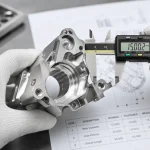
The drawing should therefore identify functional relationships instead of focusing only on individual dimensions.
Inspection may include:
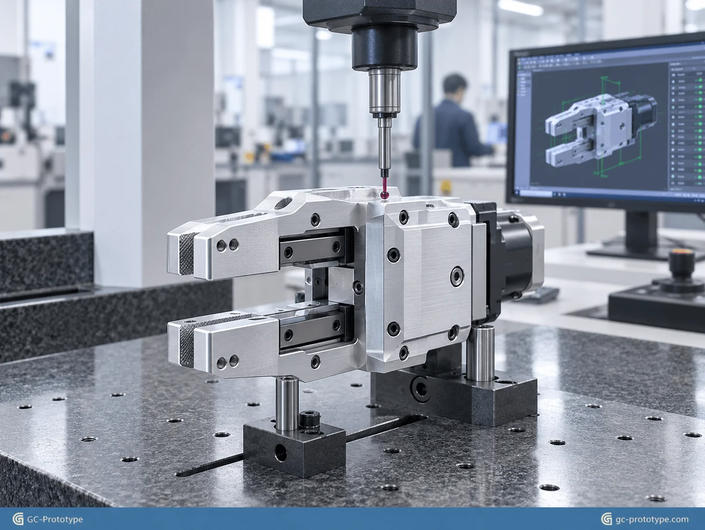
CMM measurement
Pin gauges
Bore gauges
Micrometers
Dial indicators
Functional sliding tests
For a functional gripper prototype, a combination of dimensional inspection and physical motion testing often provides the most useful engineering feedback.
CNC Machining vs 3D Printing for Functional Gripper Testing
Financial Breakdown: custom robotic gripper prototyping cost comparison
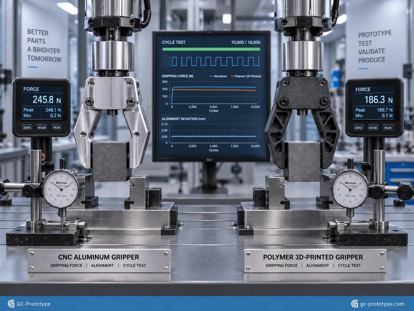
A realistic custom robotic gripper prototyping cost comparison should evaluate what the prototype needs to prove, not simply which manufacturing process provides the lowest quoted price.
For 1–10 gripper prototypes, both CNC machining and 3D printing can be useful.
| Test Requirement | CNC Metal Prototype | Polymer 3D Print |
|---|---|---|
| Geometry Verification | Excellent | Excellent |
| Very Fast Visual Iteration | Good | Excellent |
| High Gripping Force | Excellent | Material-dependent |
| Precision Sliding Fit | Excellent | More limited |
| Metal Thread Testing | Excellent | Limited |
| Wear Testing | Representative for metal design | Material-dependent |
| Complex Internal Geometry | Limited by tool access | Excellent |
| Dynamic Load Test | Strong | Material-dependent |
| Early Concept Cost | Higher | Usually lower |
When 3D Printing Is the Better Choice
3D printing is ideal during early development when engineers need to evaluate:
Overall dimensions
Finger spacing
Workpiece clearance
Cable routing
Sensor location
Basic ergonomic interaction
A low-cost printed finger can be produced quickly, tested against the workpiece, and revised before metal machining begins.
When CNC Machining Becomes Necessary
Once the engineering question changes to mechanical performance, CNC machining becomes more valuable.
Examples include:
Maximum gripping-force testing
Repeated high-speed cycling
Thread durability
Linear-guide alignment
Full-payload acceleration
Drop or impact testing
A machined aluminum component provides mechanical stiffness and interfaces much closer to the intended metal design.
Why Prototype Reliability Affects Total R&D Cost
Consider two options:
A low-cost printed gripper fails during a high-force test because the polymer finger flexes.
Engineers may not know whether the geometry is poor or whether the material simply does not represent the intended metal structure.
A CNC-machined aluminum version costs more but provides a more meaningful result.
The correct cost calculation therefore includes the value of engineering information.
Prototype cost should consider:
Manufacturing price
Engineering time
Repeat testing
Design delays
Replacement prototypes
If a more representative prototype prevents several unnecessary design revisions, its higher purchase price may reduce overall development cost.
For GC Prototype, this comparison is focused solely on prototype and validation quantities—not mass-production economics.
DFM Optimization & Surface Treatments
DFM Best Practices: Hard Anodizing, Weight Pockets, and Thread Durability
A good DFM review can substantially reduce the cost of a robotic gripper prototype while improving reliability.
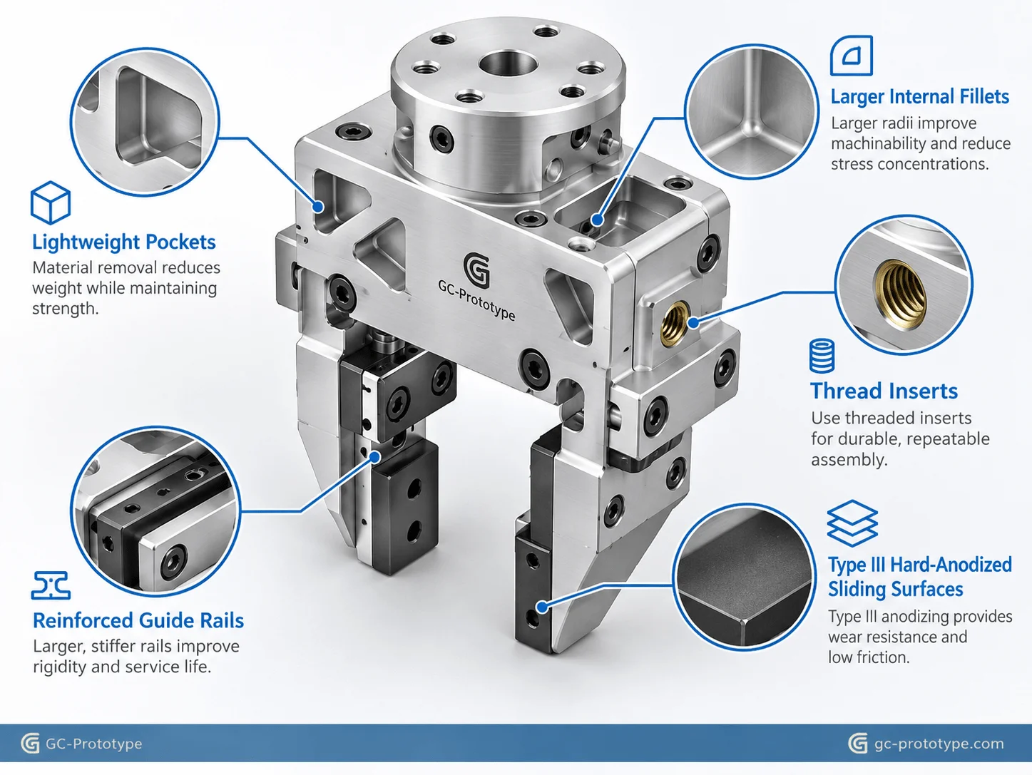
Design Practical Weight-Reduction Pockets
Removing large volumes of aluminum increases machining time.
Extremely deep pockets also require long tools that may:
Deflect
Chatter
Reduce surface quality
Require slower feed rates
Instead of maximizing pocket depth, engineers should find a practical balance between mass reduction and machinability.
Large-radius corners and shallower cavities can often provide most of the desired weight reduction at lower machining cost.
Increase Internal Corner Radii
Small internal fillets require small cutters.
A larger cutter:
Removes material faster
Is more rigid
Reduces tool-breakage risk
Where function allows, increase internal radii around weight pockets and internal cavities.
Control Thin-Wall Machining
Very thin walls may vibrate during CNC milling and distort when internal stresses are released.
Maintain additional material around:
Guide rails
Actuator mounts
Fastener holes
High-load jaw interfaces
Weight reduction should not compromise the stiffness needed for testing.
Improve Aluminum Thread Durability with Inserts
Robotic grippers are frequently assembled and disassembled during NPI.
Repeatedly installing screws into aluminum threads may eventually damage the threads, particularly where high torque is required.
Thread inserts such as Helicoil-style inserts can improve durability in selected locations.
They are useful for:
Replaceable fingers
Actuator mounts
Sensor brackets
Frequently serviced covers
Designing inserts into the prototype from the beginning can provide more realistic assembly testing.
Hard Anodizing Type III
Hard Anodizing Type III can significantly increase surface hardness and wear resistance on suitable aluminum components.
The outline highlights surface hardness values above approximately HV 400 for appropriate hard-anodized surfaces, although actual performance depends on alloy, coating specification, thickness, and processing conditions.
Potential gripper applications include:
Sliding interfaces
Jaw carriers
High-contact surfaces
Finger bodies
Guide components
However, hard anodizing changes dimensions.
Critical sliding and locating features may therefore require:
Masking
Dimensional compensation
Post-finish inspection
The anodizing requirement should be defined before machining.
| DFM Issue | Prototype Risk | Better Approach |
|---|---|---|
| Deep narrow pocket | Long cycle, chatter | Reduce depth |
| Tiny corner radius | Small cutters | Increase fillet |
| Very thin wall | Distortion | Maintain structural thickness |
| Repeated aluminum threads | Thread wear | Add inserts |
| Tight tolerance everywhere | High cost | Limit to functional interfaces |
| Late anodizing decision | Fit problems | Plan coating during DFM |
Robotic Gripper Prototype Application Scenarios
Collaborative Robot Gripper
A cobot team needs a lightweight gripper for repeated pick-and-place testing.
The aluminum prototype includes:
Servo mounting interface
Precision linear guides
Lightweight pockets
Replaceable finger modules
CNC machining allows full-payload testing using realistic structural stiffness.
Fragile Glass Handling
A gripper must pick thin glass components without generating excessive localized pressure.
Engineers prototype contoured aluminum fingers with replaceable soft pads.
Several contact geometries can be machined and tested using the same gripper body.
Electronics Component Handling
A small EOAT must handle delicate electronic modules.
Precision dowel locations and machined finger profiles help engineers evaluate positioning repeatability and sensor feedback.
Irregular Housing Gripper
A robotic cell needs to pick a molded housing with an unusual curved exterior.
Custom CNC fingers reproduce the housing contour closely while maintaining high structural rigidity.
High-Force Industrial Gripper
A pneumatic gripper prototype must withstand repeated high-force cycles.
7075-T6 fingers and a hard-anodized aluminum body allow engineers to evaluate jaw deflection, guide wear, and fastener durability.
Quick-Change Gripper Finger System
An NPI team needs one actuator platform to handle several product types.
Precision dowel holes and threaded inserts allow finger sets to be exchanged rapidly while maintaining repeatable alignment.
Prototype Procurement Strategy for Robotic Grippers
For prototype sourcing, quantity should follow the engineering test plan rather than production economics.
A typical program might require:
1 concept gripper body
3 finger profiles
2 revised slider assemblies
3–5 complete functional gripper sets
There is little benefit in purchasing large quantities before the gripping geometry and mechanical interfaces are validated.
Prototype sourcing should prioritize:
DFM responsiveness
Short turnaround
Flexible quantities
Precision inspection
Engineering communication
Information to Include in an RFQ
Provide:
STEP or other 3D CAD files
2D technical drawings
Material
Prototype quantity
Critical tolerances
GD&T
Surface finish
Hard-anodizing requirement
Thread inserts
Inspection requirements
Delivery target
Clearly identify functional surfaces.
For example, a sliding guide may require much tighter control than the outside cosmetic profile.
This helps avoid unnecessary machining and inspection cost.
Match Inspection to Prototype Purpose
A preliminary gripping-shape prototype may require only basic dimensional inspection.
A prototype designed for extended cycle testing may require:
Critical-dimension reports
Guide alignment verification
Dowel-hole inspection
Surface-finish checks
The quality plan should therefore reflect the engineering objective.
Frequently Asked Questions
Why use CNC machining for robotic gripper prototypes?
CNC machining produces parts from real engineering metals, allowing teams to evaluate stiffness, gripping force, threads, sliding fits, wear, alignment, and dynamic behavior.
When should I use 3D printing for gripper development?
3D printing is excellent for early finger geometry, workpiece-clearance checks, sensor packaging, and visual iterations where final mechanical properties are not yet required.
Is 6061 or 7075 better for a gripper prototype?
6061-T6 is economical and highly machinable for general structures. 7075-T6 provides higher strength and may be preferred for high-load or aggressively lightweight finger designs.
Can CNC machining achieve ±0.005 mm gripper tolerances?
Selected critical features may be machined to this level when geometry, material, machine setup, and inspection capability support it. Such tolerances should only be applied where required.
How can CNC machining prevent gripper jamming?
Accurate guide surfaces, dowel locations, parallelism, and appropriate clearances help sliding components move smoothly without excessive side play.
Are thread inserts useful in prototype grippers?
Yes. Inserts can improve durability where aluminum components are assembled and disassembled repeatedly during development.
Does hard anodizing improve gripper wear resistance?
It can substantially improve surface hardness and wear resistance on suitable aluminum components, making it useful for selected sliding or high-contact areas.
Does hard anodizing affect tolerances?
Yes. The coating changes surface dimensions, so critical features may need masking, machining allowance, or post-treatment verification.
How can robotic gripper prototype cost be reduced?
Use practical weight pockets, larger internal radii, standard fasteners, realistic wall thicknesses, selective tight tolerances, and modular fingers instead of remachining the complete gripper.
What prototype quantity is appropriate?
CNC machining works well for one-off parts and small prototype batches, including approximately 1–10 sets depending on the engineering validation plan.
Does GC Prototype manufacture mass-production robotic grippers?
No. GC Prototype focuses on rapid prototyping and functional engineering validation parts rather than mass-production manufacturing.
What files should I send for a CNC gripper quote?
Provide 3D CAD/STEP files, drawings for critical dimensions, material, quantity, surface treatment, thread insert requirements, and inspection expectations.
A functional robotic gripper prototype must accurately represent more than geometry. It needs enough structural stiffness, dimensional stability, thread durability, and guide precision to reveal how the final mechanism behaves under realistic loads.
CNC machining gives robotics teams this level of validation without requiring production tooling.
6061-T6 and 7075-T6 aluminum allow engineers to balance weight and strength. Modular CNC fingers enable rapid comparison of different workpiece-contact strategies. Precision guide surfaces and dowel interfaces help identify potential jamming or repeatability problems, while hard anodizing and thread inserts can improve durability during extended prototype testing.
The best prototype is not necessarily the one with the tightest tolerance or most expensive material. It is the prototype that answers the engineering question accurately and quickly enough to guide the next design decision.
For GC Prototype, the objective is clear: provide prototype parts for engineering validation, not mass-production supply.
Validating your custom robotic gripper under dynamic load testing requires unyielding structural stiffness and micrometer-level sliding tolerances. Whether you are a Robotics Engineer finalizing high-speed EOAT fingers or a Sourcing Manager balancing custom prototyping costs against project deadlines, GC Prototype provides complete rapid prototyping support.