Address:
Shenzhen Bao'an District Xinqiao Subdistrict Huangpu Community Huangpu East Ring Road No. 504 Shenzhen Yuan Industrial City Building C
Work Hours:
Monday to Friday: 9AM - 21PM
Weekend: 9AM - 21PM

Address:
Shenzhen Bao'an District Xinqiao Subdistrict Huangpu Community Huangpu East Ring Road No. 504 Shenzhen Yuan Industrial City Building C
Work Hours:
Monday to Friday: 9AM - 21PM
Weekend: 9AM - 21PM

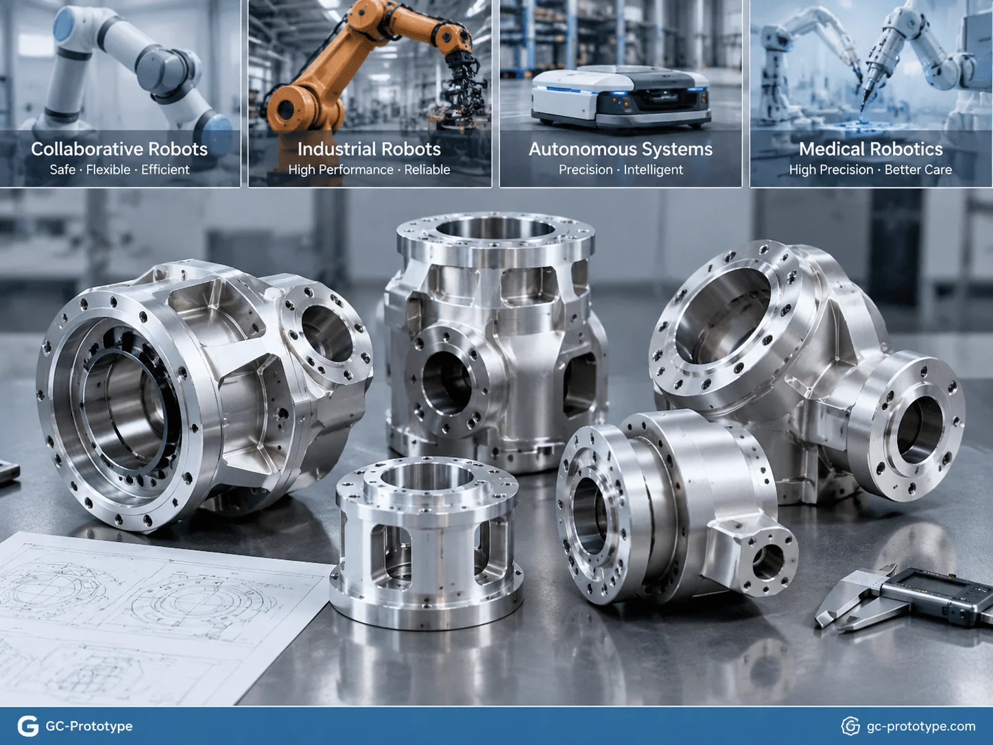
Low-volume CNC machining for robotics has become a critical manufacturing solution for companies developing advanced robotic systems during NPI, engineering validation, and pilot production stages. Modern robotic actuator modules integrate frameless torque motors, harmonic reducers, encoders, and drive electronics into compact mechanical structures, creating extremely demanding requirements for housing stiffness, heat dissipation, dimensional accuracy, and assembly consistency.
When engineers evaluate lightweight robot joint housing materials, harmonic drive mounting tolerances cnc machining, and low volume cnc machining cost for robotics, they need a manufacturing process that can deliver functional metal prototypes without the high tooling investment required by die casting or injection molding.
For Robotics Engineers, Senior Mechanical Engineers, R&D Engineers, Hardware Engineers, and Procurement Managers, low-volume CNC machining provides the flexibility needed to move from CAD design to physical testing, identify mechanical issues early, and optimize robotic joint performance before scaling toward larger production stages.
Unlike mass-production manufacturing, prototype CNC machining focuses on engineering validation, design improvement, and small-batch manufacturing flexibility. The process supports the complete product development journey from CAD design, prototype samples, functional testing, and pilot production preparation.
This article explains how precision CNC machining helps robotics companies solve key challenges including lightweight housing design, harmonic drive alignment, bearing-seat accuracy, prototype cost control, DFM optimization, and surface treatment selection.
Why Low-Volume CNC Machining Is Essential for Robot Joint Development
A robotic joint is one of the most mechanically critical components in a robotic system.
Unlike simple structural brackets, an actuator housing must simultaneously support:
Torque motor installation
Harmonic drive or RV reducer mounting
Bearing positioning
Encoder alignment
Heat dissipation
Cable routing
Structural loads
Continuous dynamic movement
During NPI and prototype validation, engineers need more than a visually accurate model. They need physical parts that represent real mechanical performance.
Typical robotic joint prototype validation includes:
Torque testing
Motion accuracy testing
Thermal testing
Vibration analysis
Bearing alignment verification
Assembly repeatability testing
Long-cycle operation testing
A common development challenge occurs when companies use early-stage prototypes that do not represent final mechanical behavior.
For example:
A 3D printed housing can help engineers verify:
Overall dimensions
Component arrangement
Cable routing
Assembly clearance
However, it cannot accurately simulate:
Aluminum thermal conductivity
Metal thread strength
Bearing-seat rigidity
Harmonic drive alignment
Structural deformation under load
When the robot enters functional testing, these differences become significant.
Low-volume CNC machining solves this problem by producing prototypes directly from engineering materials.
Common materials include:
6061-T6 aluminum
7075-T6 aluminum
Stainless steel
Titanium alloy
Engineering plastics
A typical robot joint prototype workflow includes:
1.CAD model review
2.Engineering DFM analysis
3.Material selection
4.CNC programming
5.Precision machining
6.Dimensional inspection
7.Surface finishing
8.Assembly testing
9.Functional validation
10.Design optimization
Because CNC machining does not require permanent tooling, engineers can quickly modify designs after testing.
Common prototype improvements include:
Increasing housing stiffness
Reducing unnecessary material
Adjusting motor mounting patterns
Improving cooling structures
Changing bearing positions
Optimizing cable channels
This flexibility makes CNC machining especially valuable during robotics development, where several design iterations are often required before the final architecture is confirmed.
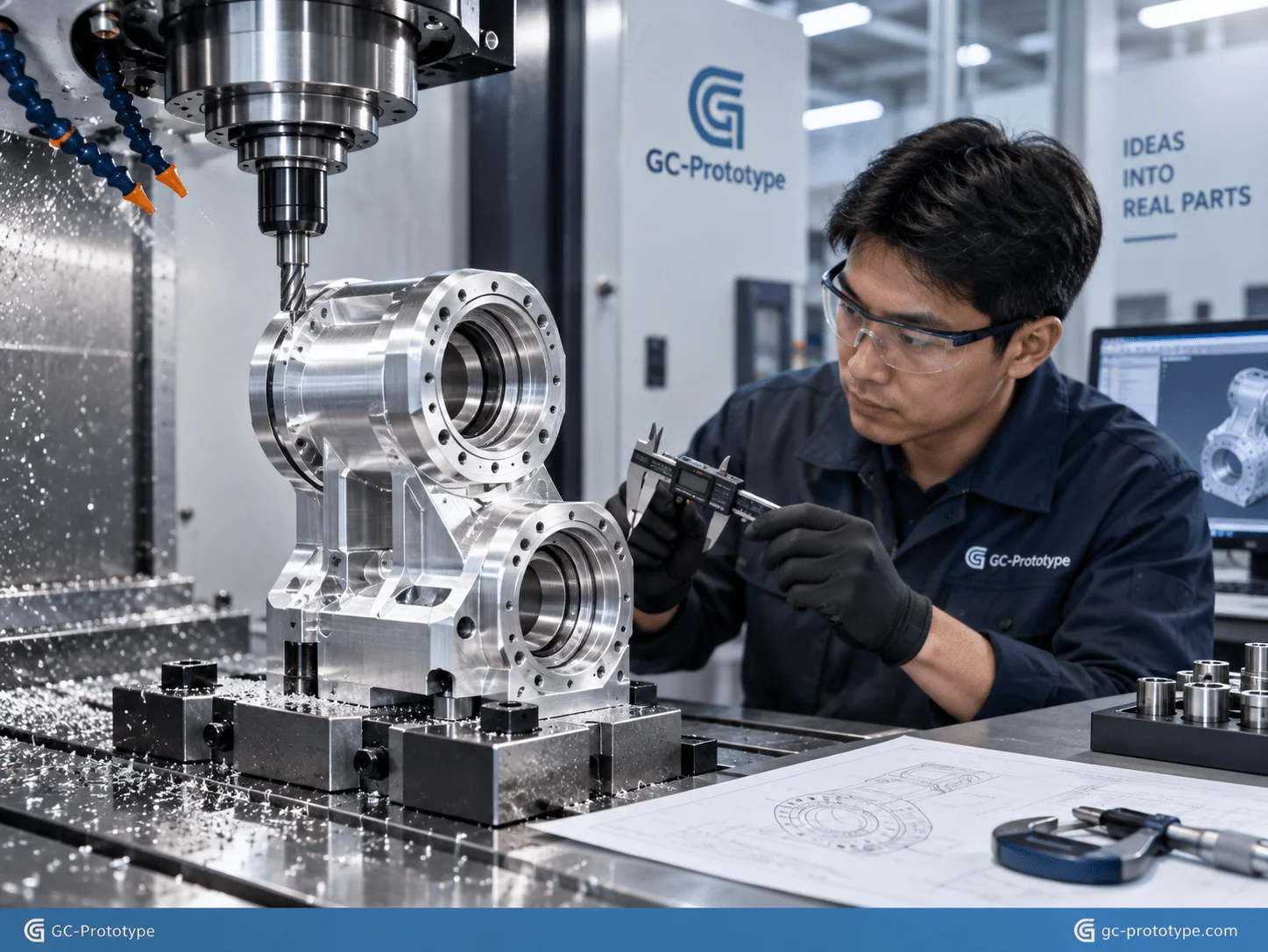
Structural Integrity & Material Selection
Thermal and Structural Optimization: Selecting lightweight robot joint housing materials
Selecting the correct lightweight robot joint housing materials is a key decision for Robotics Engineers and R&D Engineers because robot joints must achieve both high stiffness and low moving mass.
The weight of a robotic joint directly affects:
Acceleration capability
Motor torque requirements
Energy consumption
Motion stability
Payload capacity
For multi-axis robotic arms, every unnecessary gram increases inertia, especially when the mass is positioned away from the rotation axis.
Therefore, engineers must balance:
Material strength
Density
Thermal performance
Machinability
Cost
Surface treatment capability
The most commonly selected prototype materials are aviation-grade aluminum alloys, especially 6061-T6 and 7075-T6.
6061-T6 vs 7075-T6 Aluminum for Robot Joint Housings
| Property | 6061-T6 Aluminum | 7075-T6 Aluminum |
|---|---|---|
| Tensile Strength | Good | Excellent |
| Yield Strength | Moderate | Higher |
| Density | Low | Low |
| Machinability | Excellent | Very Good |
| Thermal Conductivity | Better | Lower |
| Corrosion Resistance | Excellent | Moderate |
| Material Cost | Lower | Higher |
| Typical Use | General actuator housings | High-load lightweight structures |
6061-T6 Aluminum for Prototype Actuator Housings
6061-T6 aluminum is one of the most widely used materials for robotic prototypes.
Advantages include:
Excellent CNC machinability
Good thermal conductivity
Strong corrosion resistance
Easy anodizing capability
Lower material cost
Typical applications include:
Motor housings
Encoder brackets
Sensor mounts
Prototype covers
General actuator structures
For many robotic joint prototypes, 6061-T6 provides sufficient mechanical performance while maintaining reasonable development costs.
It is particularly suitable during early engineering validation when companies need to test:
Mechanical assembly
Thermal behavior
General structural performance
7075-T6 Aluminum for High-Load Robotic Joints
7075-T6 aluminum provides significantly higher strength compared with 6061-T6.
It is often selected for applications requiring:
Higher stiffness
Reduced wall thickness
Lower structural weight
Improved strength-to-weight ratio
Typical applications include:
High-torque robotic joints
Lightweight robotic arms
Aerospace-inspired automation systems
High-speed moving components
By using 7075-T6, engineers may reduce material thickness while maintaining structural rigidity.
This helps decrease:
Joint inertia
Motor load
Energy consumption
However, stronger material does not always mean better overall performance.
The correct selection depends on:
Prototype purpose
Expected load
Testing requirements
Budget limitations
For thermal validation or early mechanical testing, 6061-T6 may provide the best cost-performance balance.
For high-speed dynamic robotic systems, 7075-T6 may provide greater value.
Five-Axis CNC Machining for Lightweight Housing Structures
Modern robot joint housings often require complex geometries, including:
Thin-wall structures
Internal cable channels
Cooling fins
Weight-reduction pockets
Multi-directional mounting surfaces
Five-axis CNC machining enables manufacturers to create these features with fewer setups.
Benefits include:
Better positional accuracy
Reduced setup error
Improved surface quality
More complex geometry capability
For actuator housings, reducing the number of machining setups is especially important because multiple precision features often need to maintain accurate relationships.
For example:
A harmonic drive mounting surface, bearing seat, and motor flange must remain precisely aligned.
If these features are produced through multiple independent setups, accumulated positioning errors may affect assembly performance.
Single-setup machining strategies help improve consistency.
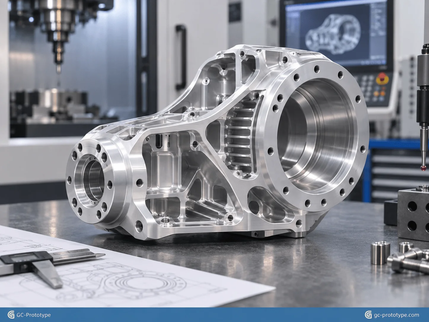
Precision Tolerances & Harmonic Drive Integration
Eliminating Backlash: Controlling harmonic drive mounting tolerances cnc machining
Controlling harmonic drive mounting tolerances cnc machining is one of the most important factors when developing high-precision robotic joints.
A harmonic drive reducer is widely used in industrial robots, collaborative robots, and precision automation equipment because it provides:
High reduction ratio
Low backlash
High positioning accuracy
Compact mechanical structure
However, the performance of a harmonic drive depends heavily on the accuracy of the surrounding mechanical interfaces.
The robot joint housing must maintain accurate relationships between:
Harmonic drive mounting surface
Bearing seat
Motor mounting interface
Output flange
Encoder reference surface
Even small deviations can create problems such as:
Gear eccentricity
Increased vibration
Uneven tooth loading
Reduced positioning repeatability
Premature component wear
For this reason, precision CNC machining is often required for prototype robot joint housings.
Harmonic Drive Interface Tolerance Control
The connection between a harmonic reducer and the housing requires careful control of:
Flatness
Parallelism
Concentricity
Surface finish
Mounting-hole position
For high-precision robotic applications, engineers commonly focus on controlling:
End-face runout
Internal diameter concentricity
Pilot diameter accuracy
Critical interfaces may require approximately:
±0.005 mm to ±0.008 mm dimensional control
depending on:
Component size
Bearing arrangement
Machine capability
Functional requirements
The objective is not to make every feature extremely tight.
The objective is to ensure that the features affecting robot accuracy are controlled correctly.
A professional tolerance strategy separates:
Critical Precision Features
Examples:
Harmonic drive locating diameter
Bearing bore
Output flange reference surface
General Manufacturing Features
Examples:
External housing profile
Cable openings
Non-functional surfaces
This approach improves both performance and manufacturing efficiency.
Establishing Correct Engineering Datums
A common mistake during robot joint design is creating drawings based only on CAD geometry rather than functional assembly requirements.
For precision robotic joints, datum selection should reflect actual mechanical operation.
Recommended references include:
Bearing axis
Harmonic drive centerline
Motor mounting plane
Output rotation axis
A proper datum structure helps:
Machinists plan setups correctly
Quality engineers inspect meaningful features
Engineers maintain assembly accuracy
Without a clear datum strategy, even individually accurate dimensions may create alignment problems after assembly.
Preventing Gear Wear and Accuracy Loss
When harmonic drive mounting surfaces are inaccurate, the reducer may experience:
Uneven loading
Increased friction
Abnormal wear
Reduced service life
During prototype testing, these issues can be difficult to identify because they may appear as:
Servo tuning problems
Controller instability
Mechanical vibration
A precision-machined housing allows engineers to separate mechanical issues from electronic control problems.
This significantly reduces debugging time during NPI.
Bearing Seat Accuracy & Precision Assembly
Achieving cnc machining tolerances for robot arm joints
Achieving cnc machining tolerances for robot arm joints is essential for maintaining smooth rotation, repeatable positioning, and long-term mechanical reliability.
Robot joints often use:
Crossed roller bearings
Angular contact bearings
Ball bearings
Precision shafts
The housing must provide accurate support for these components.
Critical bearing-seat characteristics include:
Bore diameter
Cylindricity
Roundness
Surface roughness
Coaxiality
Position accuracy
Crossed Roller Bearing Seat Requirements
Crossed roller bearings are commonly used in robotic joints because they provide:
High rigidity
Compact structure
High rotational accuracy
However, they are sensitive to installation conditions.
Poor machining accuracy may lead to:
Uneven preload
Increased friction
Reduced rotation smoothness
Lower positioning accuracy
For prototype housings, engineers should carefully control:
Bore Geometry
Including:
Diameter tolerance
Roundness
Cylindricity
Surface Quality
Typical bearing mounting surfaces may require:
Low surface roughness
Stable dimensional accuracy
The outline recommends controlling bearing-seat surface quality around Ra 0.4–0.8 μm depending on application requirements.
Advantages of Single-Setup CNC Machining
One of the biggest advantages of advanced CNC machining is reducing setup changes.
Traditional machining may require:
1.Machine one side
2.Remove the part
3.Reposition
4.Re-align
5.Machine the second side
Every repositioning introduces potential error.
For robotic joint housings, this is especially risky because many features must remain coaxial.
Single-setup machining helps:
Reduce accumulated tolerance errors
Improve alignment between bores
Increase consistency
Shorten inspection time
For example:
A housing containing two aligned bearing bores benefits significantly from machining both features under one reference setup.
This improves the probability that the final assembly maintains the intended rotation axis.
Inspection Methods for Robotic Joint Prototypes
Quality inspection should match the engineering objective.
Common inspection methods include:
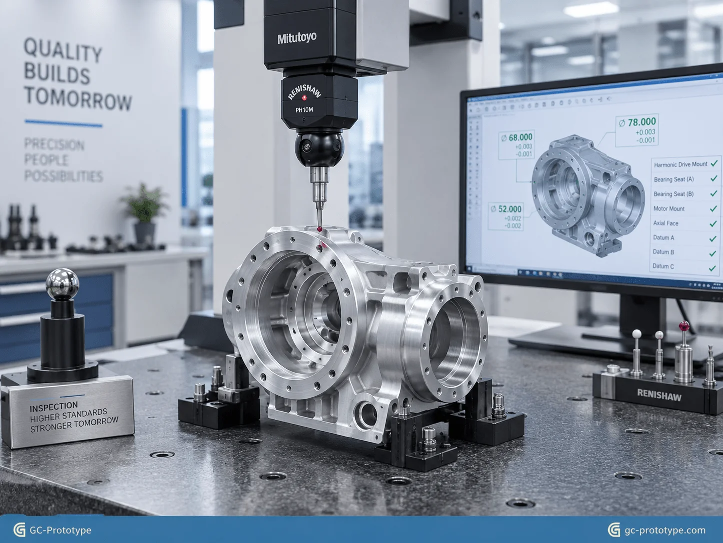
CMM Measurement
Used for:
Position accuracy
Geometric tolerances
Complex features
Bore Measurement
Used for:
Bearing seats
Precision holes
Surface Roughness Testing
Used for:
Sliding surfaces
Bearing interfaces
Assembly Verification
Used for:
Actual fit
Rotation smoothness
Mechanical function
For prototype development, inspection is not only about checking whether parts meet drawings.
It is about generating engineering confidence before moving to the next design stage.
Financial Breakdown: CNC Prototype Cost Strategy for Robotics
Understanding low volume cnc machining cost for robotics
Understanding low volume cnc machining cost for robotics is critical for CTOs, Founders, Engineering Managers, and Procurement Managers during prototype development.
Unlike mass production, prototype manufacturing focuses on:
Fast iteration
Risk reduction
Engineering validation
Flexible quantities
For robotic joint housings, CNC machining provides a major advantage because there is no expensive mold investment.
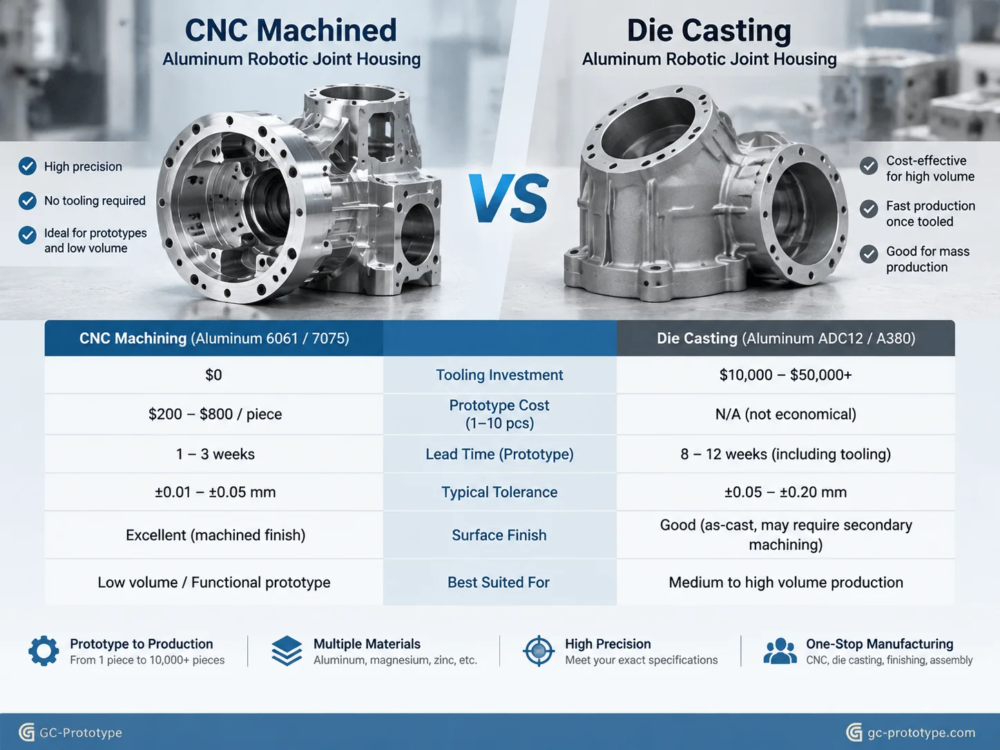
CNC Machining vs Die Casting Cost Comparison
When comparing CNC machining and die casting, companies must consider total development cost rather than only unit price.
| Cost Factor | Low-Volume CNC Machining | Die Casting |
|---|---|---|
| Mold Investment | None | High tooling cost |
| Prototype Quantity | 1–500 units | Better for larger volume |
| Design Changes | Easy | Expensive |
| Lead Time | Short | Longer |
| Material Flexibility | Wide | Limited |
| Engineering Iteration | Excellent | Poor |
| Prototype Risk | Low | Higher |
Why CNC Is More Cost-Effective During Early Development
A robotic joint design may change several times before final approval.
Typical design changes include:
Bearing position adjustment
Housing reinforcement
Weight reduction
Cooling improvements
Cable routing modifications
With CNC machining:
The company only updates:
CAD model
Manufacturing program
With die casting:
The company may need:
Tool modification
Mold repair
Additional validation
Longer waiting periods
During early development, these hidden costs can exceed the machining cost difference.
Total Cost of Ownership During Prototype and Pilot Production
For robotic companies, the real cost includes:
Manufacturing cost
Engineering time
Waiting time
Design change cost
Testing delay
Example:
A company produces 20 robotic joint housings.
Option A:
Use die casting.
Costs:
Expensive tooling
Long lead time
Difficult design changes
Option B:
Use CNC machining.
Costs:
Higher individual part cost
No tooling investment
Immediate design flexibility
If the design changes after testing, CNC machining may provide significantly lower total development cost.
Recommended Prototype Quantity Strategy
Different development stages require different quantities.
Initial Functional Prototype
Quantity:
1–5 sets
Purpose:
Mechanical validation
Assembly testing
Basic motion testing
Recommended:
CNC machining
Engineering Validation Stage
Quantity:
5–50 sets
Purpose:
Reliability testing
Customer demonstrations
System integration
Recommended:
Low-volume CNC production
Pilot Production Preparation
Quantity:
50–500 sets
Purpose:
Manufacturing process evaluation
Market testing
Pre-production validation
Recommended:
Combination of CNC machining and future production process evaluation
GC Prototype supports companies from CAD development through prototype manufacturing and pilot production preparation, helping engineering teams reduce risk before full-scale manufacturing.
DFM Optimization & Surface Treatment Strategies for Robot Joint Housings
A successful robotic joint prototype is not only defined by precision and mechanical performance. It must also be designed for manufacturability.
For Manufacturing Engineers, Procurement Managers, and NPI Engineers, Design for Manufacturing (DFM) optimization plays an important role in reducing prototype machining time, controlling cost, and improving delivery speed.
A well-optimized CNC design can reduce:
Programming complexity
Machining cycle time
Tool changes
Setup operations
Inspection requirements
while maintaining the performance required for engineering validation.
Engineering DFM Rules: Deep Pockets, Thread Strength, and Anodizing
Robot joint housings often contain complex features:
Deep internal cavities
Lightweight pockets
Threaded mounting holes
Bearing interfaces
Cooling structures
Cable passages
Although these features improve robot performance, poor design decisions can increase manufacturing difficulty.
The following DFM strategies help balance performance and manufacturability.
Optimize Internal Pocket Design and Corner Fillets
Weight reduction is important in robotic joints because lower moving mass improves:
Acceleration
Energy efficiency
Servo response
Dynamic performance
However, excessive pocket depth and small internal corners can increase CNC machining difficulty.
Small internal corner radii require:
Smaller cutting tools
Lower cutting speeds
More machining passes
This increases:
Machining time
Tool wear
Manufacturing cost
A better approach is designing practical internal radii.
Advantages include:
Faster machining
Better tool stability
Improved surface quality
Lower prototype cost
For robotic actuator housings, engineers should focus material removal in low-stress areas while maintaining sufficient strength around:
Bearing supports
Harmonic drive mounting surfaces
Motor mounting zones
Structural ribs
The goal is not creating the lightest possible housing.
The goal is creating the best balance between:
Weight
Stiffness
Machining efficiency
Avoid Excessively Deep Cavities
Deep cavities are common in lightweight robotic housings.
However, very deep pockets create several manufacturing challenges:
Long cutting tools
Reduced tool rigidity
Increased vibration
Poor surface finish
Long tools can deflect during machining, causing:
Dimensional variation
Surface quality issues
Longer machining cycles
Instead of extremely deep cavities, engineers can consider:
Multiple shallow pockets
Optimized rib structures
Alternative wall thickness designs
This approach improves both machining reliability and structural performance.
Strengthening Aluminum Threads with Helicoil Inserts
Robot joint prototypes often require repeated assembly and disassembly.
Examples include:
Motor replacement
Encoder adjustment
Gearbox testing
Cable maintenance
Direct aluminum threads may experience wear after repeated installation cycles.
Adding threaded inserts such as Helicoil inserts improves:
Thread durability
Assembly reliability
Service life
Recommended applications:
Motor mounting holes
Gear reducer mounting points
Removable covers
Frequently serviced components
This is especially valuable during prototype validation because engineers may repeatedly assemble and modify the joint structure.
Hard Anodizing Type III for Wear Protection
Surface treatment plays an important role in robotic joint performance.
Hard anodizing Type III is commonly used for aluminum components requiring:
Higher surface hardness
Better wear resistance
Improved corrosion protection
Potential applications include:
Sliding interfaces
Robot arm links
Joint housings
Guide surfaces
The outline highlights hard anodizing Type III as a strategy to improve wear resistance and corrosion protection for aluminum robot components.
However, engineers should consider coating thickness before machining.
Because anodizing changes surface dimensions, critical features may require:
Masking areas
Machining allowance
Post-treatment inspection
Examples include:
Bearing seats
Precision bores
Sliding surfaces
A professional CNC supplier should review finishing requirements during the quotation stage rather than after machining is completed.
DFM Optimization Checklist for Robotic Joint CNC Machining
| Design Issue | Potential Problem | Recommended Solution |
|---|---|---|
| Small internal radius | Slow machining | Increase fillet radius |
| Deep narrow pocket | Tool vibration | Reduce depth or redesign |
| Thin unsupported walls | Machining deformation | Add reinforcement ribs |
| Excessive tight tolerances | Higher cost | Apply only to critical features |
| Aluminum threads | Wear after repeated assembly | Use inserts |
| Late anodizing decision | Fit problems | Plan coating early |
Robotic Joint Prototype Application Scenarios
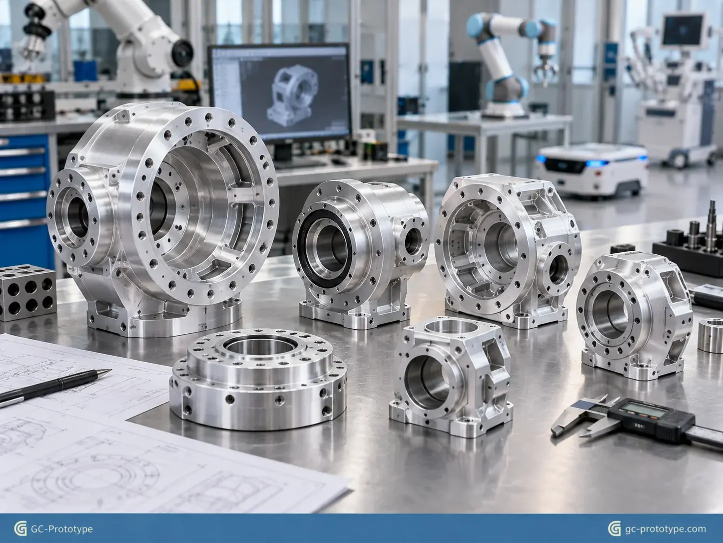
Low-volume CNC machining supports many robotic applications where companies need functional prototypes before final production decisions.
Because robotic systems often require multiple design iterations, CNC machining provides the flexibility needed during development.
Industrial Robot Arm Joint Prototype
Industrial robot manufacturers often develop high-load articulated joints requiring:
High stiffness
Precise reducer mounting
Accurate bearing alignment
Long operating life
A CNC-machined aluminum housing allows engineers to validate:
Torque capacity
Structural deformation
Thermal behavior
Assembly accuracy
before moving toward production manufacturing.
Collaborative Robot Joint Development
Collaborative robots require compact, lightweight, and safe mechanical structures.
Prototype CNC machining helps engineers test:
Reduced-weight housings
Compact actuator integration
Collision behavior
Joint movement accuracy
Materials such as 6061-T6 and 7075-T6 aluminum allow teams to compare different structural designs quickly.
Autonomous Mobile Robot Actuator Housing
Autonomous robots often require compact joints for:
Steering mechanisms
Suspension systems
Robotic wheels
Articulated platforms
CNC prototype housings allow engineers to verify:
Motor installation
Gear alignment
Environmental protection
Mechanical reliability
before field testing.
Medical Robotics Joint Prototype
Medical robotics requires extremely high precision and repeatability.
Applications include:
Surgical robotic arms
Laboratory automation robots
Precision positioning systems
Prototype CNC machining allows teams to validate:
Smooth movement
Structural stability
Component integration
Mechanical accuracy
before further product development stages.
Research and Development Robotics Platforms
Universities, research laboratories, and robotics startups often require customized mechanical systems.
Typical requirements include:
One-off prototype parts
Fast design iteration
Custom actuator housings
Experimental structures
Low-volume CNC machining provides a practical bridge between concept design and advanced testing.
Prototype Sourcing Strategy for Robotics Companies
Choosing the right CNC machining partner directly affects robotics development speed.
The lowest machining price is not always the best choice.
For engineering prototypes, companies should evaluate:
Technical communication
DFM capability
Inspection ability
Material knowledge
Prototype experience
Delivery reliability
A good prototype supplier should help engineers identify potential issues before manufacturing begins.
Recommended RFQ Information for Robot Joint Prototypes
To receive an accurate CNC quotation, engineers should provide:
3D CAD Files
Recommended formats:
STEP
IGES
SolidWorks
Other common CAD formats
Technical Drawings
Include:
Critical dimensions
Tolerance requirements
GD&T information
Surface finish requirements
Material Requirements
Specify:
Aluminum grade
Stainless steel
Engineering plastic
Surface Treatment
Specify:
Anodizing type
Color requirements
Masking requirements
Inspection Requirements
Define:
Critical measurement points
CMM requirements
Inspection reports
Clear technical information allows suppliers to optimize machining processes and avoid unnecessary cost.
Frequently Asked Questions About CNC Robot Joint Prototypes
Why is CNC machining preferred for robot joint prototypes?
CNC machining produces functional metal prototypes that accurately represent real mechanical behavior, including stiffness, thermal performance, bearing alignment, and assembly accuracy.
Can 3D printing replace CNC machining for robotic joints?
3D printing is useful for early design validation, but CNC machining is usually preferred when engineers need:
Metal strength
Precision interfaces
Load testing
Thermal validation
What is the best material for robotic joint housings?
6061-T6 aluminum is suitable for many prototype applications because of its machinability and cost efficiency.
7075-T6 aluminum is preferred when higher strength and lower weight are required.
How important are harmonic drive mounting tolerances?
Extremely important.
Incorrect mounting accuracy can lead to:
Increased backlash
Vibration
Gear wear
Reduced positioning accuracy
What CNC tolerances are needed for robot arm joints?
Critical features such as:
Bearing seats
Reducer interfaces
Motor alignment surfaces
require tighter tolerances than general housing areas.
The correct tolerance depends on the mechanical function.
How can companies reduce low-volume CNC machining costs?
Effective methods include:
Optimizing pocket design
Increasing internal radii
Reducing unnecessary tight tolerances
Using standard threads
Planning finishing requirements early
Is hard anodizing necessary for robot joint housings?
Not every application requires it.
Hard anodizing is useful when components need:
Better wear resistance
Improved corrosion protection
Higher surface hardness
Does GC Prototype provide mass production?
GC Prototype supports the complete development process from:
CAD design → prototype samples → engineering validation → pilot production → production transition.
The company provides CNC machining and prototype manufacturing support, helping customers move toward production readiness.
Accelerate Robotics Development with Precision CNC Prototypes
Developing advanced robotic systems requires manufacturing solutions that balance speed, accuracy, and engineering reliability.
Low-volume CNC machining provides robotics companies with a powerful method to transform CAD concepts into functional metal prototypes.
By selecting suitable lightweight robot joint housing materials, controlling cnc machining tolerances for robot arm joints, optimizing harmonic drive mounting tolerances cnc machining, and managing low volume cnc machining cost for robotics, engineering teams can reduce development risks and accelerate product innovation.
The biggest advantage of CNC prototyping is flexibility.
Before investing in production tooling, companies can:
Test real materials
Validate mechanical performance
Improve designs
Confirm assembly processes
Reduce future manufacturing risks
GC Prototype supports customers from initial CAD concepts through prototype manufacturing and pilot production preparation.
Whether you are developing industrial robots, collaborative robots, autonomous systems, or precision automation equipment, reliable prototype machining can significantly shorten your development cycle.
Scaling your robotic actuator housings from initial functional validation to low-volume pilot production requires uncompromising dimensional precision and reliable turnaround times. Whether you are a Senior Mechanical Engineer optimizing harmonic drive mounting tolerances or a Sourcing Manager evaluating low volume CNC machining costs for robotics, GC Prototype provides professional precision machining support.