Address:
Shenzhen Bao'an District Xinqiao Subdistrict Huangpu Community Huangpu East Ring Road No. 504 Shenzhen Yuan Industrial City Building C
Work Hours:
Monday to Friday: 9AM - 21PM
Weekend: 9AM - 21PM

Address:
Shenzhen Bao'an District Xinqiao Subdistrict Huangpu Community Huangpu East Ring Road No. 504 Shenzhen Yuan Industrial City Building C
Work Hours:
Monday to Friday: 9AM - 21PM
Weekend: 9AM - 21PM

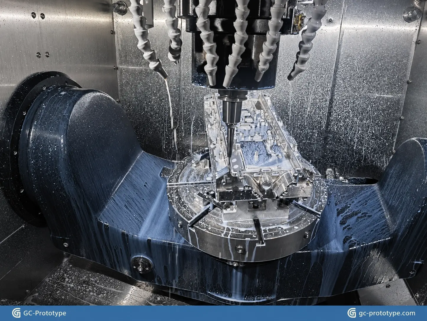
CNC complex machining parts often involve intricate geometries, deep cavities, thin walls, multiple machining surfaces, and demanding dimensional relationships. For OEM engineers and product developers, manufacturing these components requires more than selecting a CNC machine. It requires careful design for manufacturability (DFM), stable workholding, suitable machining sequences, and appropriate inspection methods.
When dealing with precision cnc machining & mold manufacturing, even small design decisions can affect machining accessibility, production time, dimensional accuracy, and overall cost.
At GC-Prototype, we support complex component development through custom CNC milling, CNC turning, 5-axis machining, EDM, and other manufacturing processes. Our engineering approach connects CAD review, prototype samples, functional validation, low-volume pilot production, and ongoing production support.
This guide explains how to manufacture complex CNC components, select suitable machining processes, optimize challenging geometries, and evaluate suppliers for demanding OEM projects.
Complex components often combine several challenging features within a single design. These features may require different cutting tools, workholding arrangements, machining directions, and inspection methods.
Understanding these challenges before production helps engineers select appropriate manufacturing strategies.
Some components require machining on several sides, with holes, slots, mounting surfaces, and profiles positioned at different angles.
Typical examples include:
Aerospace structural components.
Robotic actuator housings.
Precision industrial brackets.
Complex aluminum enclosures.
Mechanical fixtures and tooling components.
Machining these features may require multiple workpiece orientations or multi-axis CNC equipment.
Every additional setup introduces another positioning requirement. A well-planned machining strategy should consider how multiple surfaces can be completed while maintaining consistent datum references.
Deep pockets and narrow cavities can restrict cutting tool access.
Long-reach tools may experience increased deflection and vibration, potentially affecting dimensional accuracy and surface finish.
Important considerations include:
Pocket depth-to-width ratio.
Tool diameter and cutting length.
Tool rigidity.
Chip evacuation.
Roughing and finishing sequences.
Where the component’s function allows, adjusting pocket geometry can make machining more efficient.
Thin-wall components are particularly sensitive to cutting forces and clamping pressure.
During machining, excessive cutting forces or uneven material removal can cause deformation. Internal stresses released during machining may also affect dimensional stability.
This is especially important for lightweight aluminum housings, precision covers, and structural components.
A suitable machining sequence, balanced material removal, and stable workholding can help reduce these risks.
Complex parts may include cross-holes, angled bores, undercuts, internal grooves, and non-standard profiles.
These features can create challenges involving tool accessibility, positional accuracy, and inspection.
The manufacturing process should be selected according to the actual geometry rather than assuming that every feature can be produced using conventional milling alone.
Design for Manufacturability (DFM) is one of the most important steps when preparing complex components for CNC production.
A design that works well in CAD does not necessarily translate into an efficient machining process. Reviewing tool access, workholding, material removal, and inspection requirements before production can prevent unnecessary complications.
Deep, narrow pockets often require long-reach cutting tools, which can increase vibration and reduce machining efficiency.
When the design allows, consider:
Increasing pocket width.
Reducing unnecessary pocket depth.
Avoiding excessively narrow internal channels.
Providing adequate clearance for cutting tools.
These changes can improve tool accessibility and reduce machining time.
Sharp internal corners are difficult to produce using conventional rotary cutting tools because milling cutters have circular cutting profiles.
Adding appropriate internal radii can allow standard tooling to be used and reduce the need for specialized machining operations.
The selected radius should be compatible with the mating component, assembly requirements, and functional geometry.
Thin walls can deform during machining, particularly when the component contains large pockets or unsupported sections.
Consider whether the design can accommodate:
More uniform wall thickness.
Additional structural support.
Reduced unnecessary material removal.
Suitable machining allowances.
A balanced roughing and finishing sequence.
For critical thin-wall structures, engineering review should consider both material behavior and the proposed workholding method.
Undercuts, narrow grooves, and inaccessible internal features can require specialized tooling or secondary processes.
Before finalizing a design, evaluate whether these features are functionally necessary.
If an undercut is essential, consider whether it can be manufactured using suitable extended tooling, multi-axis machining, or EDM.
Not every dimension needs the same tolerance level.
Applying unnecessarily tight tolerances across an entire component can increase machining time, inspection requirements, and production costs.
Instead, identify the dimensions that directly affect:
Assembly alignment.
Bearing or shaft fit.
Sealing surfaces.
Mounting interfaces.
Functional positioning.
Clearly defined datum references and geometric dimensioning and tolerancing (GD&T) requirements also help manufacturers plan machining and inspection operations.
| Original Design Problem | Suggested DFM Improvement | Potential Benefit |
| Deep, narrow pockets | Increase width or optimize depth | Better tool accessibility |
| Sharp internal corners | Apply suitable internal radii | Improved cutter compatibility |
| Unsupported thin walls | Improve support and machining sequence | Reduced deformation risk |
| Excessively tight tolerances | Prioritize functional dimensions | Lower manufacturing costs |
| Difficult undercuts | Evaluate alternative geometry or EDM | More practical manufacturing |
| Multiple datum transfers | Establish consistent reference surfaces | Improved positional consistency |
For additional design considerations, engineers can also review our CNC machining DFM guidelines.
Different component geometries require different manufacturing strategies. Selecting the appropriate process can improve efficiency without sacrificing functional requirements.
3-axis CNC milling is suitable for many components with accessible surfaces and relatively straightforward geometries.
However, parts with multiple angled surfaces, complex contours, or features positioned around several sides may benefit from 4-axis or 5-axis machining.
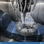
5-axis machining can provide access to multiple surfaces with fewer repositioning operations, depending on the component geometry and machine setup.
Common applications include:
Complex aluminum housings.
Robotic structural components.
Precision mechanical fixtures.
Aerospace-related components.
Multi-face industrial parts.
The decision between 3-axis and 5-axis machining should consider geometry, accessibility, tolerances, workholding, and total manufacturing cost.
Components with cylindrical features, concentric bores, threads, and rotational profiles are often suitable for CNC turning.
For parts that combine rotational and milled features, mill-turn capabilities or secondary milling operations may be considered.
Examples include precision shafts, threaded connectors, cylindrical housings, and mechanical interfaces.
Sinker EDM uses electrical discharge to remove electrically conductive material through a shaped electrode.
It can be useful for features that are difficult to access with conventional cutting tools, particularly in complex mold components and precision tooling.
Potential applications include:
Deep and narrow cavities.
Internal ribs.
Complex mold details.
Small internal profiles.
Features with restricted tool access.
Wire EDM uses a continuously moving wire electrode to cut electrically conductive materials.
It is commonly considered for precision profiles, intricate contours, and mold-related components.
It can be particularly useful when the required geometry cannot be efficiently produced through conventional milling.
CNC machining and EDM do not necessarily compete with each other. They can complement one another within a single manufacturing project.
For example, a mold insert may first undergo CNC rough machining to remove the majority of the material. Sinker EDM can then produce specific deep or narrow features that are difficult to machine conventionally.
This combination allows manufacturers to select the most suitable method for each feature.
| Machining Process | Suitable Components | Main Advantage | Key Consideration |
| 3-Axis CNC Milling | Plates, brackets, simple housings | Flexible machining | Multiple setups may be required |
| 5-Axis CNC Milling | Multi-face and complex components | Access to multiple surfaces | Programming and setup complexity |
| CNC Turning | Shafts, bushings, cylindrical parts | Efficient rotational machining | Best suited to rotational geometries |
| Sinker EDM | Deep cavities and narrow internal features | Access to difficult geometries | Requires conductive materials and electrodes |
| Wire EDM | Precision profiles and inserts | Accurate profile cutting | Requires suitable through-cut geometry |
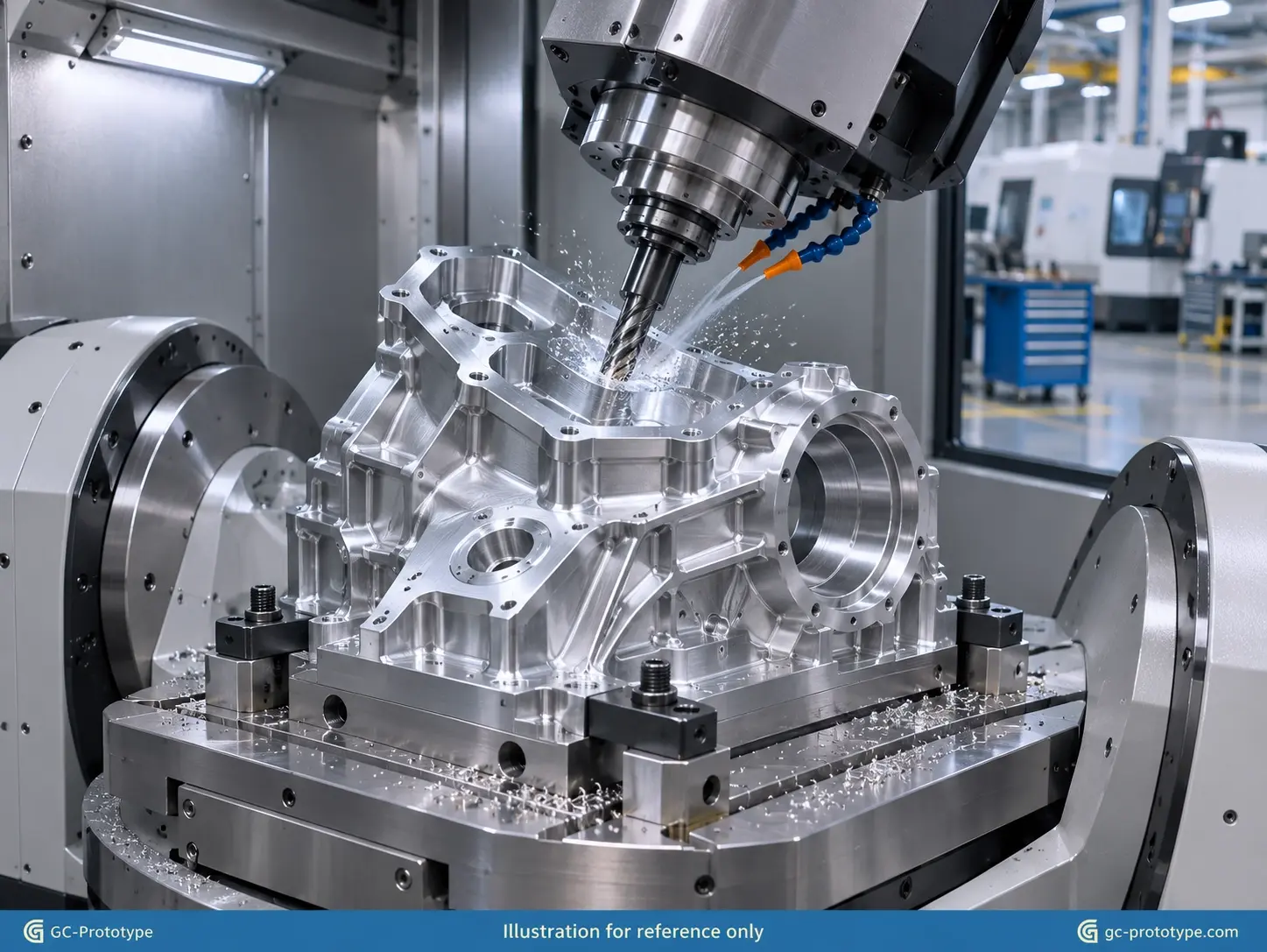
Mold components frequently contain complex geometries and functional surfaces that require carefully controlled manufacturing processes.
For OEM manufacturers and tooling developers, component quality can influence mold assembly, alignment, and subsequent molding performance.
Mold bases and plates may require multiple mounting holes, alignment features, pockets, and precision reference surfaces.
CNC milling can produce these features according to engineering drawings.
Important manufacturing considerations include:
Hole positioning.
Plate flatness requirements.
Mounting interface dimensions.
Reference surfaces.
Material selection.
Inspection requirements.
The machining sequence should be planned to maintain dimensional relationships between functional features.
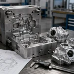
Mold cores and cavity inserts often contain detailed profiles, pockets, and mating surfaces.
Their geometry may require a combination of CNC milling, drilling, finishing, and EDM.
A suitable process plan should consider the accessibility of each feature, material characteristics, and required surface finish.
Some mold details, including narrow ribs, deep cavities, and intricate internal profiles, may be difficult to manufacture using conventional milling.
EDM can provide an alternative for these electrically conductive mold components.
The decision to use EDM should consider electrode design, feature geometry, material, surface requirements, and inspection criteria.
Mold components frequently contain several interacting dimensions.
A small dimensional variation in a critical interface may affect assembly or the relationship between mating components.
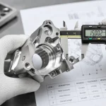
Inspection planning should therefore focus on functional dimensions, geometric relationships, and drawing-defined requirements.
For projects involving mold-related components, CNC machining can also be coordinated with rapid tooling and injection molding services when the product development requirements call for them.
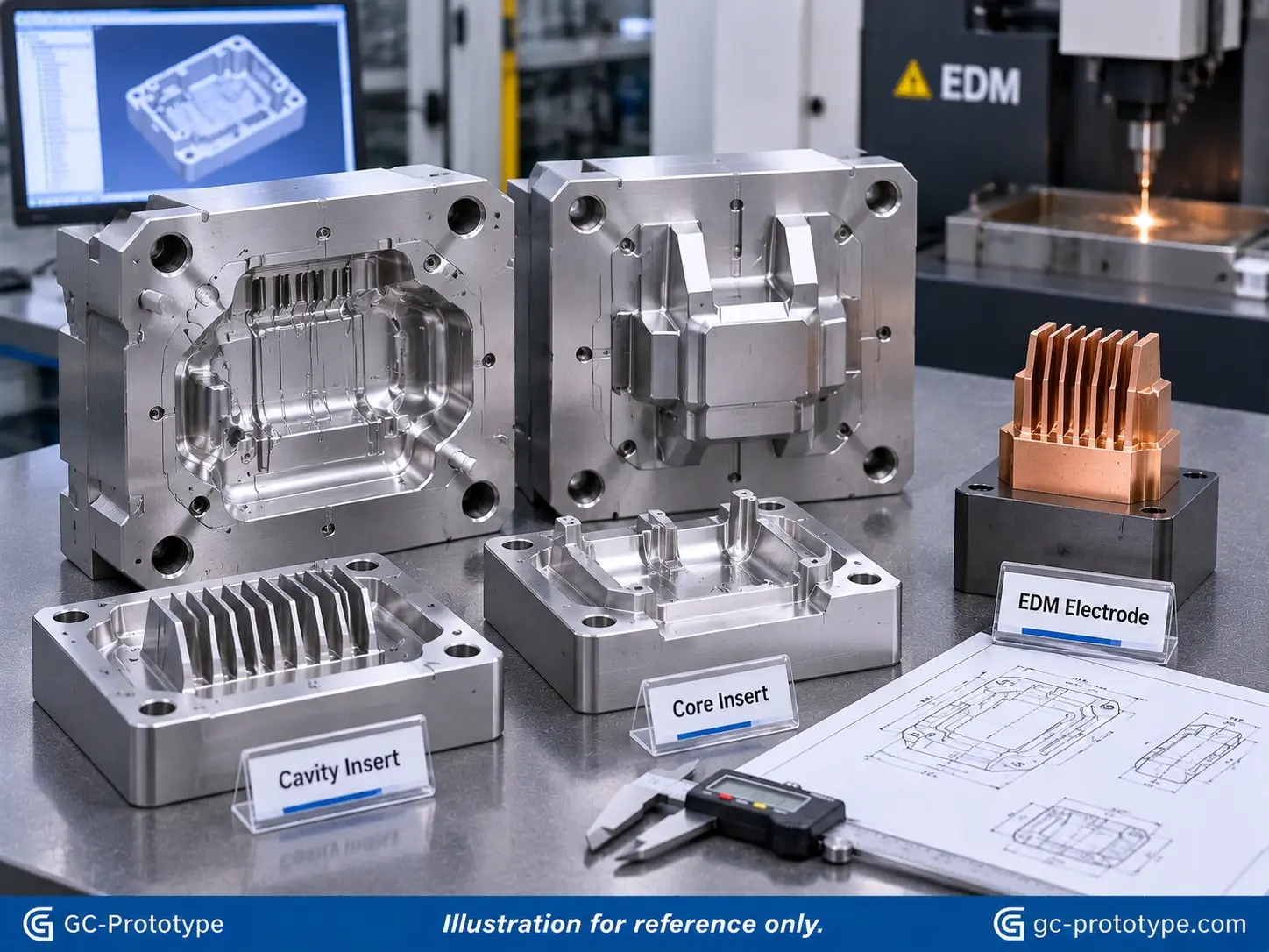
Complex CNC manufacturing is used across industries where components must combine structural strength, precise interfaces, and specialized geometries.
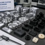
GC-Prototype supports custom machining projects involving different materials and component configurations.
Aluminum housings often contain deep pockets, mounting holes, threaded features, and thin-wall sections.
They are commonly used in electronic equipment, industrial automation, and mechanical assemblies.
DFM review should consider wall thickness, material removal, mounting interfaces, and finishing requirements.
Stainless steel components may include internal bores, intersecting holes, threaded connections, and complex external profiles.
Material selection and machining strategy should account for the grade’s cutting characteristics and the required surface condition.
These components may be used in industrial equipment, fluid-handling systems, and mechanical assemblies.
Robotic components may require accurate bearing seats, mounting interfaces, angled features, and multiple reference surfaces.
The positional relationship between these features can be important for assembly and mechanical movement.
A suitable machining and inspection strategy should prioritize functional interfaces rather than treating every dimension equally.
Industrial machinery often uses custom brackets, fixtures, structural components, and mechanical housings.
These parts may combine milled surfaces, drilled holes, threaded features, and non-standard profiles.
Choosing an appropriate process helps balance manufacturing efficiency with functional requirements.
| Application | Common Complex Features | Manufacturing Considerations |
| Aluminum Housings | Deep pockets and thin walls | Tool access and deformation control |
| Stainless Steel Components | Internal bores and intersecting holes | Cutting strategy and inspection |
| Robotic Housings | Bearing seats and angled interfaces | Datum control and alignment |
| Industrial Fixtures | Multiple locating surfaces | Workholding and dimensional consistency |
| Mold Inserts | Deep cavities and narrow ribs | CNC and EDM integration |
Even when suitable CNC equipment is available, workholding and machining sequence remain important factors in manufacturing complex parts.
An unstable setup or poorly planned sequence can affect dimensional consistency and surface quality.
The fixture must hold the workpiece securely while providing access to the required machining surfaces.
For thin-wall or irregularly shaped components, clamping pressure and support locations should be carefully considered.
Suitable fixtures can help reduce movement and deformation during cutting.
Complex components may require machining from several orientations.
Using consistent datum references helps maintain relationships between holes, surfaces, and mating features.
The engineering drawing should clearly identify functional reference surfaces and important geometric relationships.
Roughing and finishing should be planned as separate stages when the component geometry and material behavior require it.
Roughing removes the majority of excess material, while finishing establishes the required dimensions and surface condition.
For some complex parts, allowing material to stabilize between operations can help manage deformation risks.
Deformation can result from cutting forces, internal stresses, excessive clamping, and uneven material removal.
A carefully planned machining sequence can help minimize these effects.
The appropriate approach depends on the material, component geometry, wall thickness, and dimensional requirements.
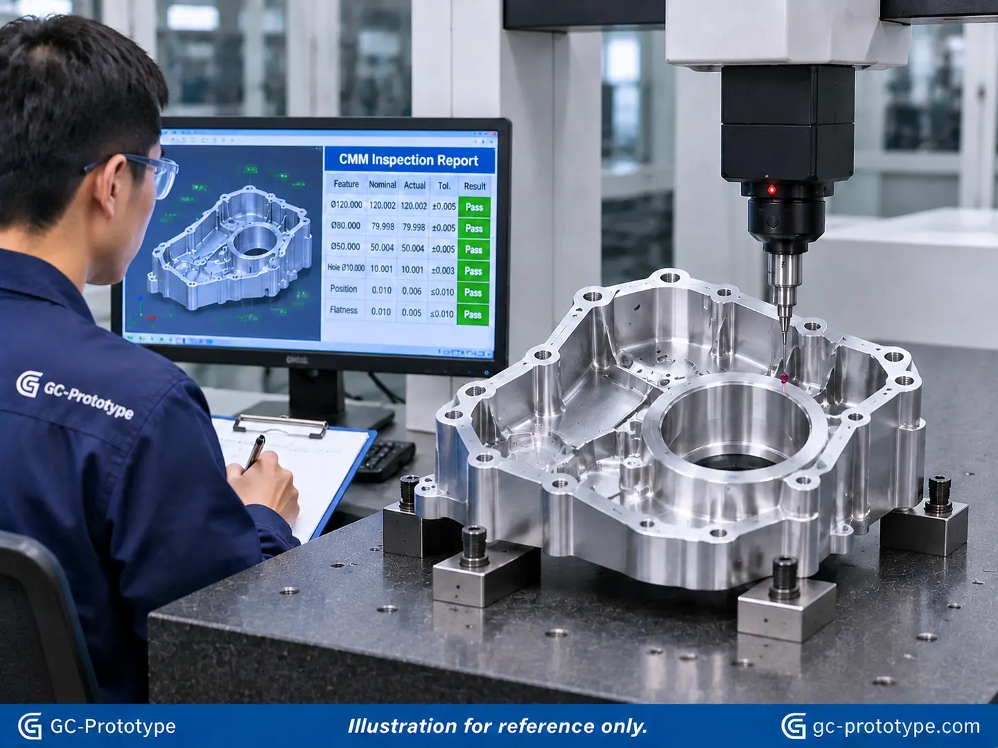
The cost of complex CNC components is influenced by more than the raw material price.
Several manufacturing factors can significantly affect the final quotation.
| Cost Factor | Why It Increases Cost | Optimization Approach |
| Multiple Setups | Additional setup and alignment time | Consolidate operations where practical |
| Deep Cavities | Longer tools and slower cutting | Optimize pocket geometry |
| Thin Walls | Additional support and finishing | Improve structural design |
| EDM Electrodes | Electrode production and setup | Simplify electrode geometry |
| Tight Tolerances | More process control and inspection | Apply tolerances by function |
| Complex Finishing | Additional processing operations | Specify only necessary finishes |
Every additional setup may involve fixture preparation, alignment, and dimensional verification.
When possible, consider whether a suitable multi-axis machining strategy can reduce unnecessary repositioning.
Specialized cutting tools and EDM electrodes may increase preparation costs.
Designing features around practical tooling requirements can help reduce unnecessary complexity.
Large amounts of material removal can increase machining time, particularly when components contain deep pockets or complex internal structures.
Optimizing component geometry may help reduce unnecessary material removal.
Complex parts may require additional dimensional checks, deburring, finishing, and assembly preparation.
Clearly identifying critical requirements during the quotation stage helps manufacturers estimate the complete manufacturing scope.
Complex components often require more than a single machining operation. Their manufacturing process should support product development and subsequent production requirements.
GC-Prototype follows a project workflow that connects engineering review with prototype manufacturing and production planning.
The manufacturer reviews the 3D model and 2D drawings to evaluate material selection, feature accessibility, tolerances, workholding, and manufacturing methods.
Initial components are produced using the selected processes to verify geometry, dimensions, and material requirements.
The customer evaluates whether the prototype meets its intended assembly and functional requirements.
After design validation, the project can move into a small production batch where process consistency and inspection requirements are reviewed.
For projects requiring larger quantities, manufacturing methods and production requirements can be reassessed according to expected demand.
This CAD-to-production approach helps OEM customers coordinate their development stages without repeatedly changing manufacturing partners.
A detailed Request for Quotation (RFQ) helps manufacturers understand the component’s geometry, technical requirements, and production expectations.
When requesting a quotation for complex CNC components, buyers should prepare the following information.
Provide a 3D CAD model in STEP, STP, or IGES format, together with a 2D engineering drawing showing dimensions, tolerances, and drawing revision.
Identify important dimensions, datum references, and GD&T requirements.
If certain features directly affect assembly performance, clearly highlight them.
Specify the material grade, condition, and any required surface treatment.
Include surface roughness requirements when a numerical finish specification is necessary.
Provide prototype quantity, expected production quantity, inspection requirements, and target delivery schedule.
| RFQ Information | Recommended Details |
| 3D CAD Model | STEP / STP / IGES |
| 2D Engineering Drawing | PDF with revision |
| Material | Exact material grade |
| Critical Features | Deep pockets, thin walls, complex surfaces |
| Tolerances | Critical dimensions and GD&T |
| Surface Finish | Required surface finish specifications |
| Quantity | Prototype and production quantities |
| Inspection | Dimensional inspection report |
| Delivery | Destination and target schedule |
Providing complete technical information makes it easier to evaluate manufacturing feasibility and prepare an accurate quotation.
CNC complex machining parts are components with challenging geometries or manufacturing requirements, such as multiple machining surfaces, deep cavities, thin walls, intersecting holes, and precision interfaces. They often require carefully planned machining sequences, specialized tooling, or multiple manufacturing processes.
5-axis machining may be beneficial when components contain multiple angled surfaces, complex contours, or features that are difficult to access through conventional setups. However, not every complex component requires 5-axis machining. The best approach depends on geometry, tolerances, workholding, and manufacturing cost.
DFM helps identify design features that may increase machining time or require specialized tooling. Optimizing internal radii, pocket geometry, wall thickness, tolerances, and datum references can improve manufacturability and reduce unnecessary operations.
Yes. CNC machining can remove the majority of material and produce accessible surfaces, while EDM can create selected deep, narrow, or intricate features in electrically conductive materials. Combining these processes can provide a practical solution for certain complex mold components.
Deep cavities require suitable tool reach, rigidity, chip evacuation, and cutting parameters. Thin-wall structures require careful workholding, balanced material removal, and appropriate finishing sequences to help reduce deformation. The specific approach depends on the material and component geometry.
Yes. CNC machining is suitable for producing functional prototypes and low-volume batches without requiring dedicated production molds for every component. It can also support manufacturing planning as a product moves from prototype validation toward subsequent production.
Manufacturing complex components requires a practical understanding of geometry, material behavior, machining accessibility, workholding, and inspection requirements.
GC-Prototype provides CNC machining, turning, EDM, and other manufacturing processes to support custom component development and low-volume production projects.
Whether you need precision housings, complex mold components, mechanical parts, or custom industrial components, our team can review your drawings and help evaluate suitable manufacturing approaches.
Send us your 3D CAD model and engineering drawings, together with:
Required material grade.
Critical dimensions and GD&T requirements.
Surface finish specifications.
Prototype or production quantity.
Inspection and documentation requirements.
Target delivery schedule.
Our engineering team can review your project requirements and provide feedback on manufacturing feasibility and quotation details.