Address:
Shenzhen Bao'an District Xinqiao Subdistrict Huangpu Community Huangpu East Ring Road No. 504 Shenzhen Yuan Industrial City Building C
Work Hours:
Monday to Friday: 9AM - 21PM
Weekend: 9AM - 21PM

Address:
Shenzhen Bao'an District Xinqiao Subdistrict Huangpu Community Huangpu East Ring Road No. 504 Shenzhen Yuan Industrial City Building C
Work Hours:
Monday to Friday: 9AM - 21PM
Weekend: 9AM - 21PM

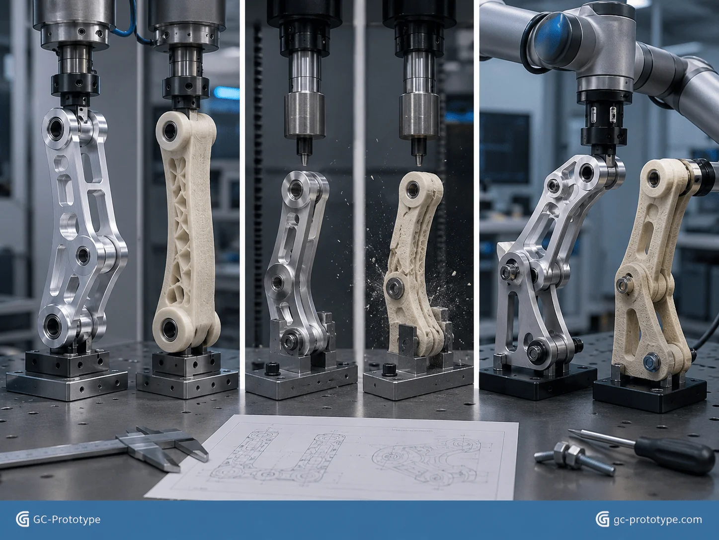
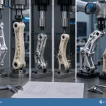
Prototype CNC Machining gives robotics teams a direct path from CAD design to high-load functional testing using real engineering metals. When evaluating prototype cnc machining vs 3d printing for robotic arms, polymer prints are excellent for geometry checks and early fit validation, but they may not reproduce the stiffness, thread strength, thermal behavior, or bearing-interface stability required for realistic robotic-arm testing. For NPI programs involving high-speed motion, repeated acceleration, torque shocks, and precision positioning, CNC-machined aluminum prototypes provide the mechanical reliability engineers need before a design is finalized.
For Robotics Engineers, Senior Mechanical Engineers, NPI Engineers, and Sourcing Managers, the key challenges are reducing moving mass, maintaining structural rigidity, controlling joint alignment, and producing custom parts fast enough to support continuous design iteration. This guide focuses specifically on prototype and small prototype-batch manufacturing—not mass production—and explains material selection, multiaxis machining, joint tolerances, process economics, DFM, and sourcing strategy for robotic-arm development.
Why CNC Machining Is Critical for Robotic-Arm Prototyping
A robotic arm is a dynamic mechanical system. Its structural components must perform under conditions that appearance prototypes cannot fully represent.
Typical validation activities include:
Full-payload lifting
High-acceleration motion
Emergency-stop impact
Repeated joint cycling
Gearbox alignment testing
Bearing preload verification
Thermal-rise testing
Servo tuning
Vibration analysis
End-effector positioning tests
During these tests, the stiffness of each arm link, joint housing, motor flange, and end-effector interface affects the complete kinematic chain.
A component that deflects by a small amount near the base of the arm may create a much larger positioning deviation at the tool center point. This is one reason why material realism matters during functional validation.
CNC machining allows engineers to prototype with materials such as:
6061-T6 aluminum
7075-T6 aluminum
Stainless steel
Titanium
POM
PEEK
Other engineering plastics
Unlike casting or molding, prototype CNC machining does not require dedicated production tooling. When testing reveals a problem, the engineering team can revise the CAD model and machine another iteration.
A typical robotic-arm prototype workflow may look like:
CAD and load-case review
DFM analysis
Material selection
CNC milling and/or turning
Dimensional inspection
Anodizing or required finishing
Mechanical assembly
Dynamic testing
Engineering revision
This makes CNC machining particularly valuable during NPI, when design stability is more important than optimizing for high-volume manufacturing.
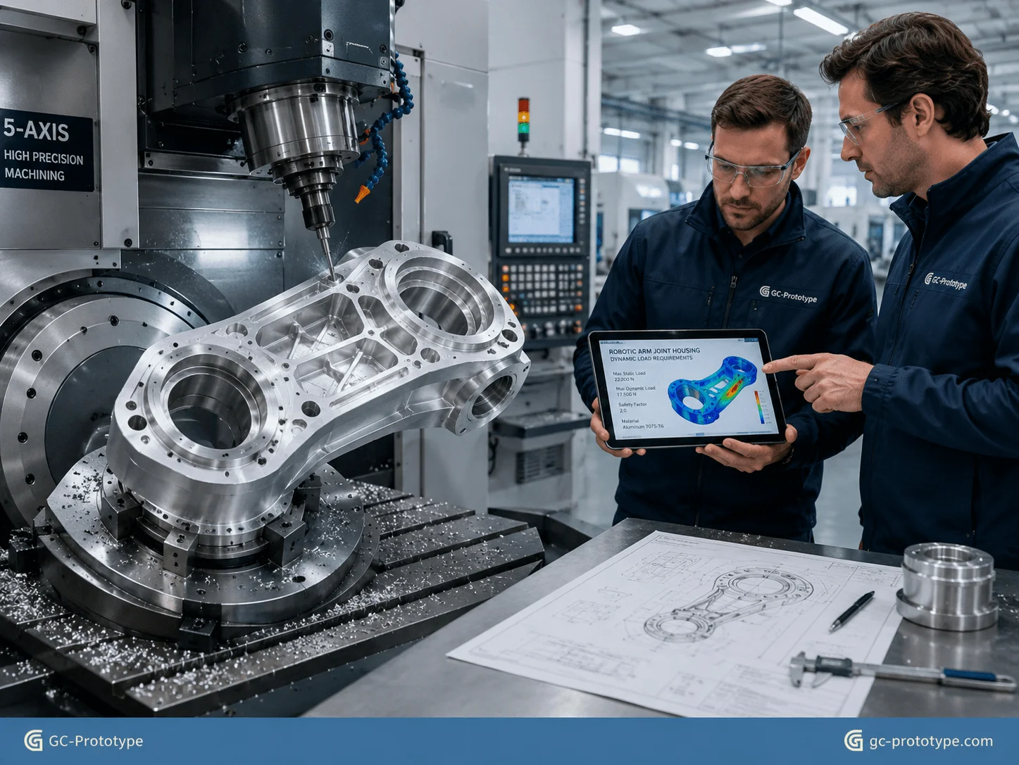
Lightweight Materials & Structural Design
High Strength-to-Weight Ratio: Harnessing lightweight 7075 aluminum machining for robotic arms
Using lightweight 7075 aluminum machining for robotic arms is particularly valuable when engineers need to reduce inertia without sacrificing structural strength.
A robotic arm constantly accelerates and decelerates. The farther mass is located from the joint axis, the greater its effect on rotational inertia. Excessive moving mass can require:
Larger servo motors
Higher torque
More energy
Slower acceleration
More aggressive controller tuning
Reducing arm mass can therefore improve both mechanical performance and control response.
Two common aluminum choices are 6061-T6 and 7075-T6.
| Engineering Factor | 6061-T6 | 7075-T6 |
|---|---|---|
| Strength | Good | Much higher |
| Machinability | Excellent | Excellent |
| Corrosion resistance | Very good | Lower than 6061 |
| Cost | Lower | Higher |
| General prototyping | Excellent | Excellent for high-load parts |
| Typical use | Frames, covers, brackets | Joint structures, links, high-load parts |
6061-T6 is often the more economical choice for general-purpose robotic prototypes. It machines cleanly, anodizes well, and provides sufficient strength for many sensor brackets, electronics housings, and structural components.
7075-T6 becomes more attractive when the prototype must withstand higher loads or when reducing cross-section and weight is a priority.
For example, a forearm linkage designed in 6061 may require thicker ribs or a larger section to achieve the desired strength. A 7075 version may allow the engineer to remove more material while retaining the required load capability.
However, the strongest alloy is not automatically the best choice.
The engineering team should also consider:
Fatigue loading
Corrosion environment
Finish requirements
Thread design
Machining cost
Prototype test purpose
If the goal is simply to verify packaging and cable routing, 7075 may be unnecessary. If the prototype will undergo repeated full-payload cycling, the higher-strength alloy may provide more representative data.
Reducing Moment of Inertia Through CNC Pocketing
Weight reduction in robotic arms should be strategic.
Large deep pockets can remove significant mass from aluminum linkages, but indiscriminate material removal can reduce stiffness or cause machining distortion.
Good lightweighting focuses on removing material from low-stress regions while maintaining material around:
Bearing interfaces
Joint connections
Fastener locations
Load paths
Motor mounting zones
Finite element analysis can help identify low-stress regions before machining.
Multiaxis CNC milling can then produce:
Deep pockets
Thin-wall structures
Curved linkages
Rib networks
Internal cable channels
The goal is not maximum material removal. It is the best strength-to-weight balance for the prototype’s intended dynamic test.
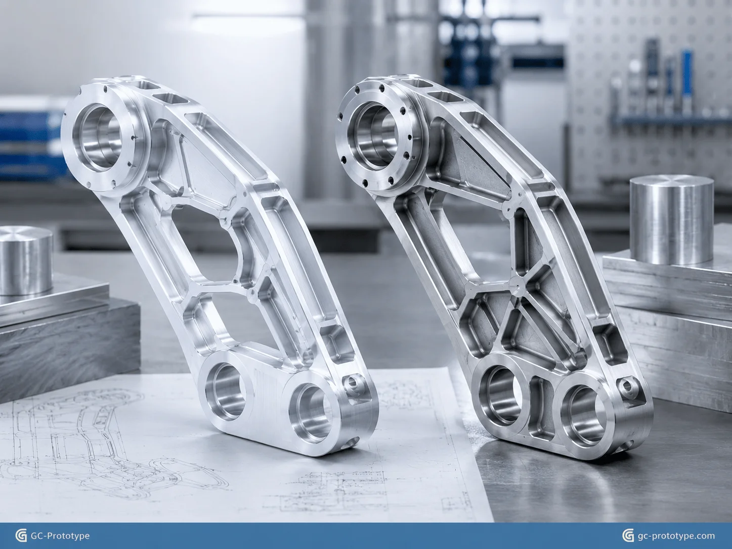
Complex Geometry: Manufacturing custom cnc machined robotic arm linkages
Manufacturing custom cnc machined robotic arm linkages allows Design Engineers and Hardware Engineers to test mechanical architectures that cannot be validated effectively with generic off-the-shelf components.
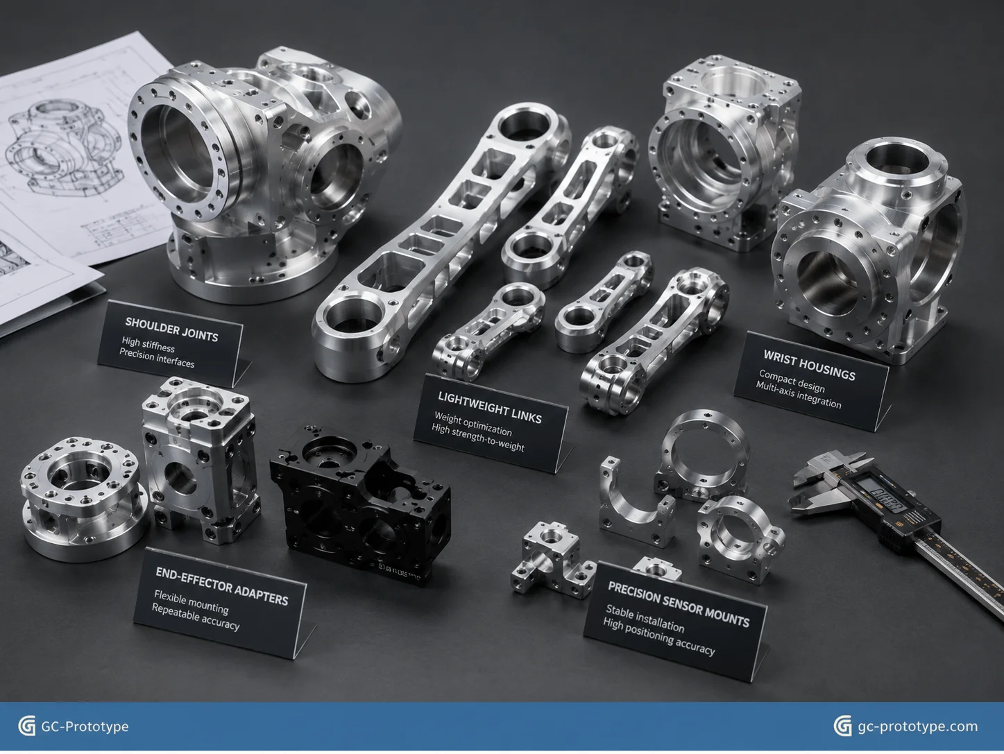
Custom robotic-arm parts may include:
Upper-arm linkages
Forearm structures
Elbow joint housings
Wrist housings
End-effector mounting plates
Motor brackets
Encoder mounts
Sensor housings
Hollow cable-routing structures
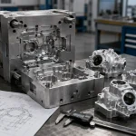
Five-axis CNC machining is particularly useful when these components combine several complex orientations.
A robotic-arm linkage may contain:
Angled mounting holes
Curved exterior surfaces
Deep internal cavities
Multiple precision bores
Complex pockets
Several datum faces
Producing these features with conventional three-axis machining may require repeated repositioning.
Every additional setup adds:
Fixture preparation
Alignment time
Programming time
Opportunity for positional variation
Five-axis machining can reduce the number of setups by allowing the tool to approach features from multiple orientations while the workpiece remains clamped.
This is especially valuable for prototype parts where the relationship between interfaces matters more than absolute cosmetic perfection.
For example, machining a gearbox mounting surface, bearing seat, and motor flange in a controlled setup can help preserve their geometric relationship.
Hollow Cable Channels and Internal Features
Robotic arms increasingly integrate:
Power cables
Encoder wiring
Pneumatic tubes
Communication cables
Hollow structures can protect these systems while reducing external cable movement.
However, internal cavities must remain machinable.
A completely enclosed curved channel may be easy to print but impossible to machine from solid material.
During DFM, engineers may split the structure, introduce removable covers, add tool access, or create channels from multiple machining directions.
Designing specifically for CNC accessibility reduces machining cost while preserving the intended functional architecture.
Precision Tolerances & Joint Assembly
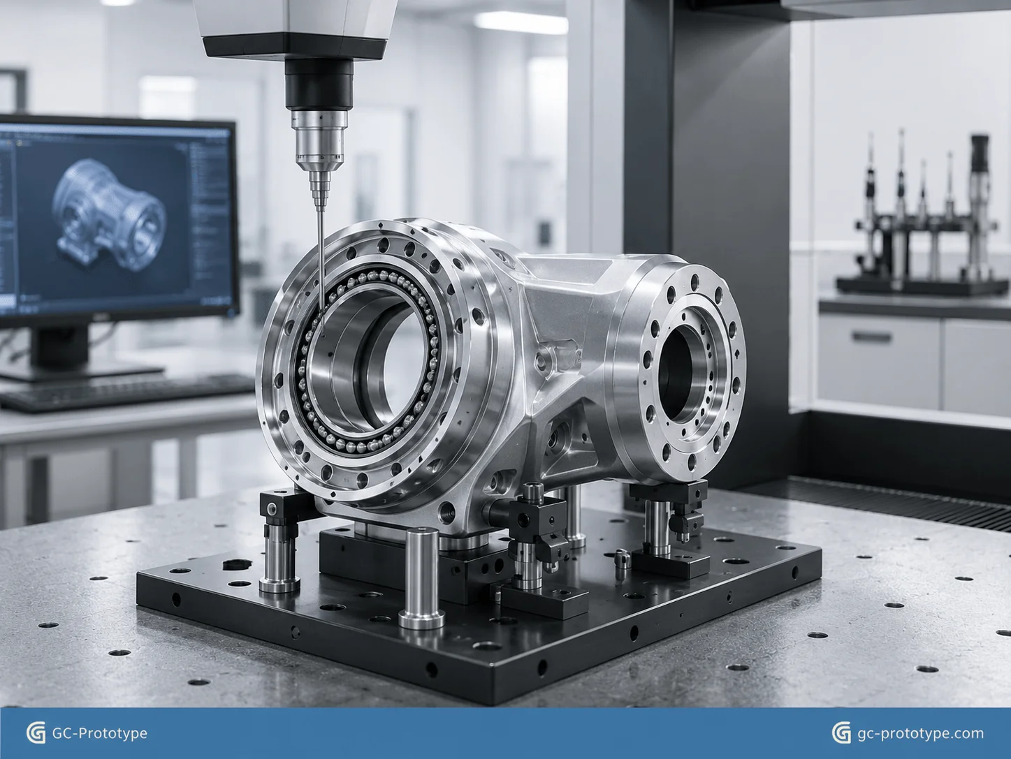
Eliminating Backlash: Controlling cnc machining tolerances for robot arm joints
Controlling cnc machining tolerances for robot arm joints is critical because small interface errors can produce measurable positioning errors at the end effector.
A typical robotic joint may combine:
Harmonic drive
RV reducer
Servo motor
Cross-roller bearing
Encoder
Output flange
Joint housing
The performance of these components depends on accurate alignment.
Critical engineering characteristics may include:
Bearing-seat diameter
Coaxiality
Face runout
Perpendicularity
Flatness
Locating-hole position
Gearbox pilot diameter
Motor flange alignment
The outline references ISO 2768-f for appropriate general tolerancing and approximately 0.008 mm-level control for selected critical joint relationships. In practice, general tolerances and critical geometric tolerances should be specified separately: the tightest values should be reserved for features that directly influence alignment and rotation.
For example:
| Feature | Recommended Engineering Priority |
|---|---|
| Cross-roller bearing seat | Critical |
| Harmonic-drive locating diameter | Critical |
| Motor flange face | Critical |
| Encoder reference surface | High |
| Cable pass-through | General |
| Cosmetic outside profile | General |
Specifying extremely tight tolerances across the entire housing can increase machine time and inspection cost dramatically.
A better approach is functional tolerancing.
Why Coaxiality Matters
Imagine a gearbox output axis and cross-roller bearing that are slightly misaligned.
The prototype may still assemble, but dynamic testing can reveal:
Increased vibration
Additional bearing load
Heat generation
Motion resistance
End-effector oscillation
These problems can be incorrectly blamed on the motor or controller when the actual cause is mechanical alignment.
High-quality CNC prototyping allows the engineering team to isolate these variables.
Datum Strategy for Robotic Joint Prototypes
A good engineering drawing should define datums that reflect actual assembly behavior.
Instead of dimensioning every feature from arbitrary CAD edges, reference:
Bearing centerlines
Gearbox mounting faces
Motor alignment surfaces
This makes inspection more meaningful.
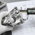
Critical components may be measured using:
CMM inspection
Bore gauges
Micrometers
Dial indicators
Surface roughness instruments
For a prototype, the inspection plan should match the test objective. A housing intended for precision repeatability testing may justify full CMM reporting, while a preliminary packaging prototype may not.
Process Trade-Offs & Prototype Cost Analysis
Functional Reliability: prototype cnc machining vs 3d printing for robotic arms
A realistic comparison of prototype cnc machining vs 3d printing for robotic arms should focus on what the prototype needs to prove.
Both processes have important roles.
| Test Requirement | CNC-Machined Metal | Polymer 3D Printing |
|---|---|---|
| Geometry check | Excellent | Excellent |
| Fast concept iteration | Good | Excellent |
| High-load testing | Excellent | Limited by material |
| Metal thread validation | Excellent | Limited |
| Bearing-seat validation | Excellent | Usually less suitable |
| Thermal behavior | Representative for metal design | Different |
| Complex internal channels | Limited by tooling | Excellent |
| Cosmetic concept model | Good | Excellent |
| Full-payload dynamic test | Strong | Often insufficient |
For early concept work, 3D printing is difficult to beat.
A designer can quickly print a joint shell or arm link to check:
Size
Appearance
Cable routing
Basic assembly
But once the test shifts from “Does it fit?” to “Does it survive realistic loads?”, material behavior becomes much more important.
Full-Payload Testing
During full-payload testing, a robotic arm experiences bending and torsional loads.
An aluminum CNC prototype provides realistic stiffness for:
Motor sizing
Structural deflection
Vibration
Servo tuning
Joint alignment
A plastic printed structure may deform significantly more, making test results less useful.
Emergency-Stop Impact
Emergency stops can create high transient loads.
The mechanical structure must absorb sudden inertia when the arm decelerates rapidly.
CNC-machined aluminum prototypes help engineers identify:
Weak sections
Fastener movement
Joint deflection
Bearing-support issues
before the design is finalized.
Thread Pull-Out & Assembly Validation
Robotic prototypes often contain many threaded joints.
Directly machined aluminum threads behave much more like the intended metal structure than polymer printed threads.
This allows engineers to validate:
Assembly torque
Fastener retention
Repeated assembly
Thread engagement
Prototype Cost Comparison
For 1–10 robotic-arm prototype sets, cost depends strongly on geometry and test goals.
3D printing may provide lower upfront cost for large, geometrically complex visual parts.
CNC machining typically costs more because it includes:
Raw metal
CNC programming
Setup
Machine time
Tooling
Inspection
Finishing
However, engineering value matters more than part price.
If a CNC prototype uncovers a joint-stiffness problem before a later manufacturing commitment, the additional prototype cost can prevent a much larger redesign.
A simple comparison:
| Cost Consideration | CNC Machining | 3D Printing |
|---|---|---|
| No mold required | Yes | Yes |
| Programming/setup | Higher | Lower |
| Material realism | High | Process-dependent |
| Precision metal interfaces | Strong | May need post-machining |
| Functional test value | High | Depends on application |
| Complex geometry cost | Can rise quickly | Often favorable |
For GC Prototype’s prototyping-focused service, the question is not how to optimize thousands of units. It is how to manufacture a small number of useful prototypes that help the engineering team make the next design decision correctly.
Procurement Strategy & DFM Optimization
Engineering DFM Checklist: Reducing Machine Time and Prototyping Overhead
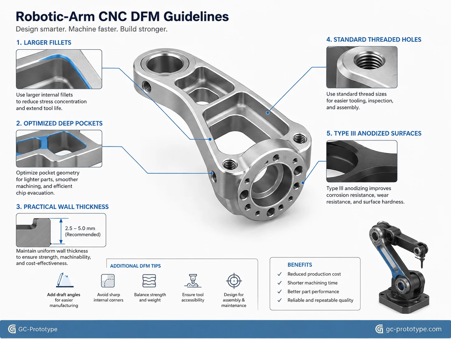
Prototype machining costs are heavily influenced by geometry. A few DFM changes can reduce machine time substantially without changing robotic performance.
Increase Internal Fillet Radii
Deep pockets with tiny corner radii require small end mills.
Small tools:
Remove material slowly
Are less rigid
Break more easily
Require additional toolpaths
If the design allows a larger fillet, the machinist can use a larger-diameter cutter and remove material faster.
For a robotic arm linkage containing extensive pocketing, this can produce meaningful savings.
Optimize Wall Thickness
Thin walls reduce weight but can become unstable during machining.
When large quantities of material are removed, residual stress may cause thin walls to:
Distort
Bow
Twist
A DFM review should preserve adequate stiffness during both machining and functional testing.
Critical areas around bearings, motors, and fasteners should usually retain more material than noncritical cosmetic regions.
Avoid Excessive Pocket Depth
A very deep cavity requires long-reach tools.
Long tools are more prone to:
Deflection
Chatter
Slow feed rates
If a pocket exists primarily for weight reduction, consider whether reducing its depth slightly provides nearly the same mass reduction with much better machinability.
Standardize Holes and Threads
Prototype robotic arms frequently use multiple fasteners and alignment pins.
Standardizing:
Metric threads
Counterbores
Reamed holes
Dowel-pin sizes
reduces tool changes and simplifies inspection.
Reduce Setups
Features positioned on many different sides of a part can increase setup time.
Where possible, arrange critical geometry so that multiaxis machining can complete it with fewer re-clamping operations.
Plan Hard Anodizing Type III Early
Hard Anodizing Type III can improve the wear resistance of suitable aluminum surfaces and is useful for selected robotics prototypes that experience sliding, repeated contact, or handling.
Potential applications include:
Joint housings
Arm linkages
End-effector components
However, anodizing changes surface dimensions.
Critical fits may require:
Masking
Dimensional allowance
Post-treatment inspection
The finish should therefore be included in the DFM review before CNC machining begins.
| DFM Problem | Cost / Risk | Better Strategy |
|---|---|---|
| Tiny internal fillets | Small tools, longer cycle | Increase radius |
| Deep narrow pocket | Chatter and slow cutting | Reduce depth |
| Ultra-thin walls | Distortion | Maintain practical thickness |
| Tight tolerance everywhere | High inspection cost | Restrict to critical features |
| Nonstandard threads | Extra tooling | Standardize |
| Anodizing added late | Fit problems | Plan finish before machining |
Prototype Sourcing Strategy for Robotics NPI
Sourcing robotic-arm prototypes is fundamentally different from purchasing production inventory.
The objective is learning.
A typical NPI program may require:
1 initial arm-link concept
2–3 joint-housing revisions
3 different end-effector concepts
5 complete functional test sets
There is little value in ordering large quantities of a design that may change next week.
Prototype sourcing should therefore prioritize:
Short lead time
Engineering communication
DFM support
Reliable inspection
Flexible quantities
rather than high-volume unit pricing.
Match Quantity to the Test Plan
A better procurement strategy is to manufacture only the number of parts needed for the current test.
For example:
Geometry validation:
1–2 parts may be enough.
High-load dynamic testing:
2–5 sets may be required.
Durability testing:
Additional sets may be useful where tests are destructive.
This reduces prototype inventory and keeps engineering capital focused on current validation work.
What to Include in Your Prototype RFQ
Provide:
3D CAD / STEP model
2D drawings
Material
Quantity
Critical tolerances
GD&T requirements
Surface roughness
Anodizing requirements
Inspection requirements
Target delivery date
Mark critical features clearly.
If a bearing seat requires very tight control while an outer cover does not, that distinction helps the supplier avoid unnecessary machining and inspection.
Robotic-Arm Prototype Application Scenarios
High-Torque Shoulder Joint
A robotics R&D team develops a new shoulder axis using a harmonic-drive reducer.
The CNC prototype includes:
Cross-roller bearing seat
Motor pilot
Gearbox interface
Large weight-reduction pockets
7075-T6 helps reduce moving mass while maintaining structural strength.
Lightweight Forearm Linkage
A Design Engineer needs to decrease the inertia of a long forearm.
A five-axis machined linkage includes:
Hollow regions
Internal cable routing
Angled mounting interfaces
The prototype allows dynamic testing before the geometry is frozen.
Collaborative Robot Wrist
A cobot wrist assembly requires precise bearing alignment and several angled end-effector mounting features.
Multiaxis CNC machining allows the functional interfaces to be machined with fewer setups.
End-Effector Adapter
A Hardware Engineer needs several adapters for different gripper concepts.
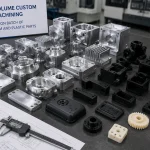
Small CNC batches allow each geometry to be tested physically without any mold investment.
Vision Sensor Mount
A robotic arm requires rigid camera positioning.
A CNC-machined aluminum sensor mount allows engineers to test vibration and optical alignment under real robot motion.
Choosing a CNC Prototyping Partner for Robotic Arms
The best prototyping supplier should provide engineering support rather than simply machine the uploaded geometry.
Useful capabilities include:
3-axis CNC milling
5-axis CNC machining
CNC turning
Aluminum and stainless machining
Precision inspection
CMM measurement
Anodizing coordination
Prototype DFM review
A qualified prototype partner should identify:
Difficult tool access
Unnecessary tight tolerances
Thin-wall distortion risk
Small internal radii
Excessive setup requirements
before manufacturing begins.
For robotic-arm development, fast engineering feedback can be as valuable as fast machining.
GC Prototype’s role is to support prototype validation and design iteration. The goal is to help robotics teams produce accurate functional parts for testing—not to supply mass-production volumes.
Frequently Asked Questions
Why use CNC machining for robotic-arm prototypes?
CNC machining produces functional prototypes from real engineering metals, allowing teams to evaluate stiffness, bearing fits, threads, alignment, heat transfer, and high-load mechanical behavior.
Is 7075 aluminum always better than 6061 for robotic arms?
No. 7075 provides higher strength, while 6061 is more economical and offers very good machinability and corrosion resistance. Material selection should follow the load case and prototype purpose.
When should I use 3D printing instead?
3D printing is excellent for fast visual concepts, cable-routing checks, ergonomic validation, and complex geometry where final mechanical properties are not yet required.
When should I switch from 3D printing to CNC machining?
Use CNC machining when you need realistic metal stiffness, bearing interfaces, high-torque tests, reliable metal threads, precision alignment, or representative thermal performance.
Can robotic-arm joint features reach 0.008 mm-level tolerances?
Selected critical features may be specified at this level when geometry, material, machine setup, and inspection capability support it. Such tolerances should not be applied indiscriminately to the entire part.
How does CNC machining reduce robotic joint backlash?
CNC machining can precisely control bearing seats, gearbox locating diameters, flange relationships, and other mechanical interfaces that influence alignment and unwanted joint clearance.
Does Type III anodizing affect precision fits?
Yes. Hard anodizing adds material to the surface and can affect bearing seats, sliding interfaces, and threads. Critical features may require masking or dimensional compensation.
How can robotic-arm prototype costs be reduced?
Use larger internal radii, practical wall thicknesses, standard threads, fewer setups, realistic tolerances, and weight-reduction pockets that remain accessible to standard cutting tools.
What quantity is suitable for robotic-arm CNC prototyping?
Prototype machining is well suited to one-off parts and small batches such as 1–10 sets, depending on the validation plan.
Does GC Prototype manufacture mass-production robotic parts?
No. GC Prototype focuses on prototype machining and functional engineering validation rather than mass-production manufacturing.
What files should I send for a quote?
Send your 3D CAD or STEP model, 2D drawings if critical tolerances are required, material, quantity, surface finish, anodizing requirements, and inspection expectations.
Prototype CNC machining gives robotic-arm engineering teams something early visual prototypes cannot always provide: realistic mechanical behavior.
By manufacturing functional linkages, joint housings, bearing interfaces, motor mounts, and end-effector components from engineering-grade aluminum, teams can evaluate dynamic stiffness, alignment, vibration, thermal behavior, and assembly before finalizing the design.
The greatest value comes from combining high-quality machining with smart DFM. Use 7075 where high strength-to-weight performance is genuinely valuable, control joint tolerances only where they affect motion accuracy, design large internal fillets and machinable lightweight pockets, and account for anodizing before critical dimensions are finalized.
For robotics NPI, the goal is not production volume. It is faster, more reliable engineering validation.
Validating your next-generation robotic arm design demands uncompromising dynamic stability, tight joint tolerances, and fast prototyping turnarounds. Whether you are a Senior Mechanical Engineer optimizing 7075 aluminum linkages or a Sourcing Manager evaluating CNC machining vs 3D printing for robotic prototypes, GC Prototype delivers precision prototyping support.