Address:
Shenzhen Bao'an District Xinqiao Subdistrict Huangpu Community Huangpu East Ring Road No. 504 Shenzhen Yuan Industrial City Building C
Work Hours:
Monday to Friday: 9AM - 21PM
Weekend: 9AM - 21PM

Address:
Shenzhen Bao'an District Xinqiao Subdistrict Huangpu Community Huangpu East Ring Road No. 504 Shenzhen Yuan Industrial City Building C
Work Hours:
Monday to Friday: 9AM - 21PM
Weekend: 9AM - 21PM

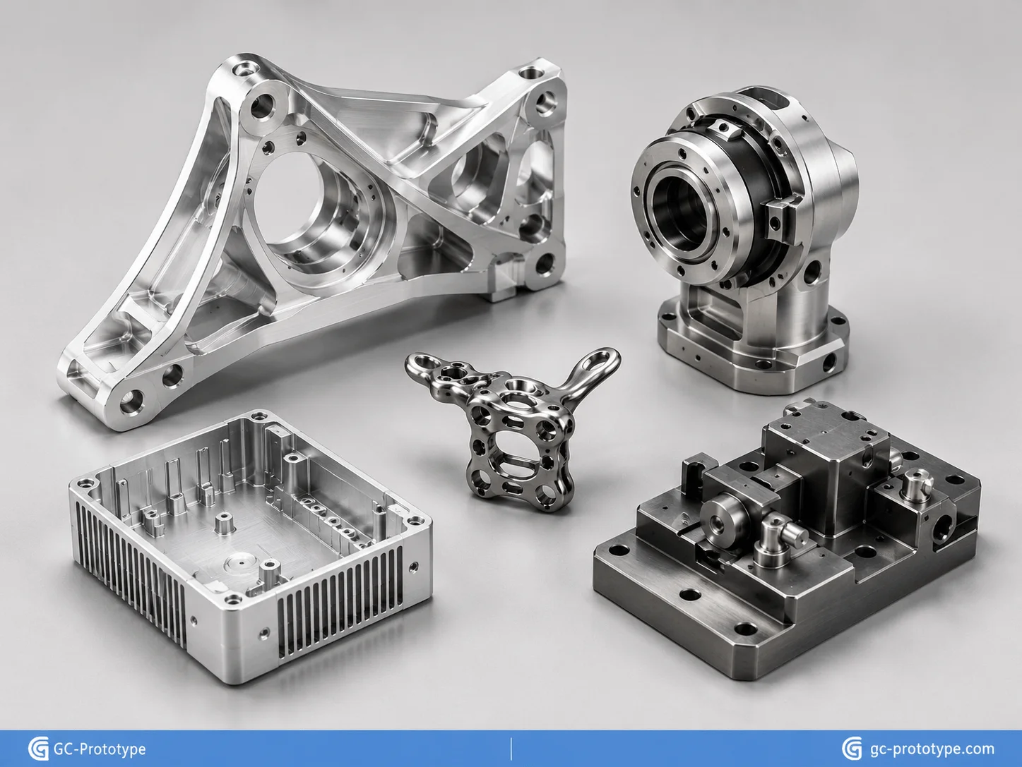
CNC machining remains one of the most important manufacturing technologies for new product introduction, engineering validation, and low-to-medium-volume production. When a component requires high mechanical strength, tight dimensional control, production-grade metals or plastics, and reliable repeatability, subtractive manufacturing often provides a more predictable result than additive or molding-based alternatives. For Senior Mechanical Engineers, Robotics Engineers, Manufacturing Managers, and Sourcing Professionals, the key challenge is not simply finding a machine shop. It is designing parts that can be manufactured efficiently, assigning tolerances that match function, selecting the right surface finish, and controlling total procurement cost from prototype through repeat production.
This guide explains five-axis machining, ISO 2768 general tolerances, surface roughness, process economics, and practical DFM rules for aerospace, medical, robotics, consumer electronics, automotive, and industrial applications. It also provides a clear framework for preparing drawings, comparing suppliers, and avoiding expensive design decisions before production begins.
Why CNC Machining Remains Essential for Precision Manufacturing
CNC machining removes material from a solid block, plate, bar, or near-net blank using programmed cutting tools. Milling, turning, drilling, grinding, and EDM may be combined to manufacture a complete part. Unlike injection molding or die casting, machining does not require a dedicated production mold, which makes it suitable for prototypes, engineering builds, customized components, and quantities that do not justify hard tooling.
CNC machining is especially valuable when a project requires:
High-strength aluminum, stainless steel, titanium, brass, copper, PEEK, POM, or other engineering materials
Tight fits for bearings, seals, dowels, shafts, or optical components
Low production quantities with frequent revisions
Complex geometry requiring several cutting orientations
Production-like surfaces and mechanical behavior
Traceability, inspection reports, or controlled finishing
However, machining cost is strongly influenced by geometry. A visually simple part can become expensive if it contains deep narrow cavities, extremely thin walls, tiny internal radii, hard-to-reach side features, or unnecessarily tight tolerances. Early DFM review is therefore one of the most effective ways to protect budget and lead time.
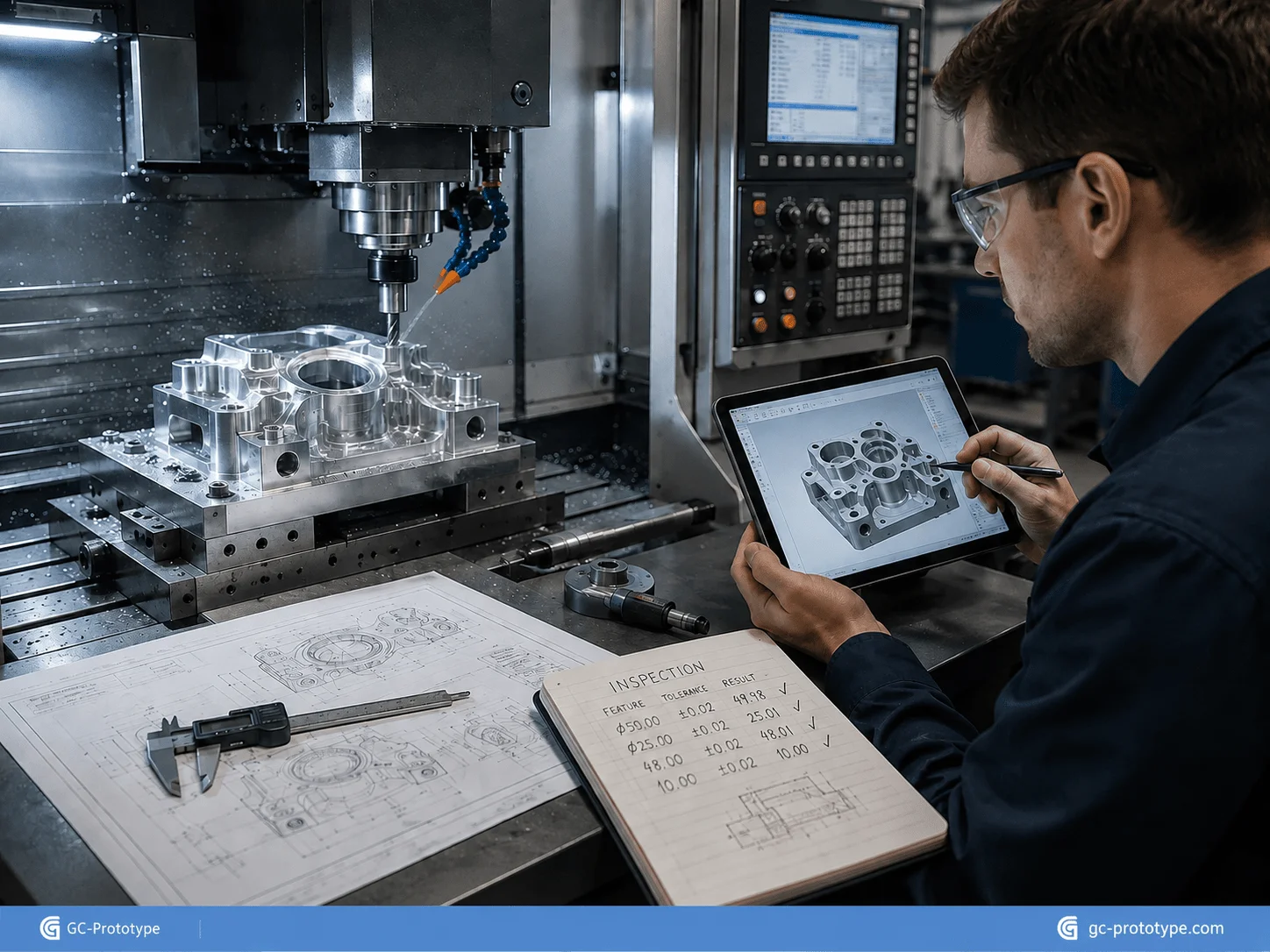
Industry Applications & Precision Standards
Aerospace and Defense Innovations: Harnessing 5 axis cnc machining for aerospace components
Using 5 axis cnc machining for aerospace components allows manufacturers to produce lightweight brackets, structural interfaces, UAV parts, actuator housings, sensor mounts, impellers, and complex test hardware with fewer setups than conventional three-axis machining.
A five-axis machine moves the cutting tool or workpiece along three linear axes and two rotational axes. This enables access to multiple faces, compound angles, and contoured surfaces in one controlled setup. The greatest benefit is not simply geometric freedom. It is the ability to maintain relationships between features without repeatedly removing and repositioning the part.
Every setup change introduces potential datum-transfer error. A bracket with angled bores, machined pads, and a curved mounting surface may require several fixtures on a three-axis machine. A five-axis process may complete the same geometry from one primary workholding position, improving positional accuracy and reducing inspection complexity.
Aerospace components frequently use 6061-T6 or 7075-T6 aluminum for favorable strength-to-weight performance. Titanium alloys may be selected for higher strength, temperature resistance, or corrosion performance, although they machine more slowly and increase tool wear. Material certificates, first-article inspection, surface-treatment records, and lot traceability may be required depending on the program.
| Evaluation Factor | Three-Axis Machining | Five-Axis Machining |
| Best geometry | Prismatic plates, brackets, simple housings | Multi-face parts and complex contours |
| Setup count | Often higher | Often lower |
| Programming | Simpler | More advanced |
| Tool access | Limited by fixed orientation | Improved access from multiple angles |
| Tool rigidity | Long tools may be necessary | Shorter tools can often be used |
| Typical cost | Lower for simple parts | Better value when complexity justifies it |
Five-axis machining should not be specified automatically. A simple plate with top-side pockets and perpendicular holes is usually more economical on a three-axis machine. The correct decision depends on total setup time, fixture complexity, tolerance relationships, surface requirements, and annual quantity.
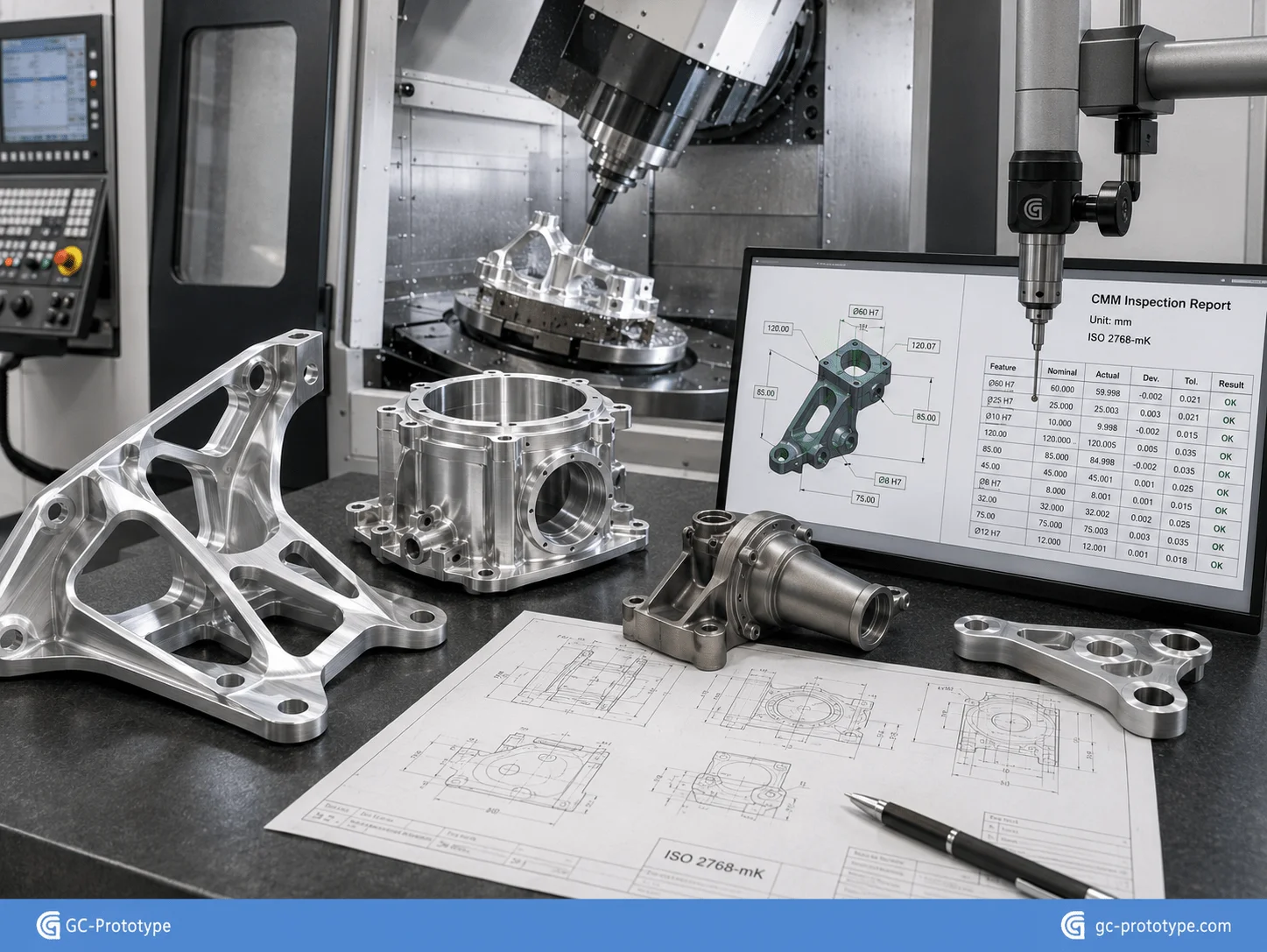
Technical Precision: Understanding cnc machining tolerance standards iso 2768
Understanding cnc machining tolerance standards iso 2768 helps engineers communicate reasonable general tolerances without placing a separate limit on every non-critical dimension. ISO 2768 is commonly referenced on mechanical drawings to define general tolerances for dimensions that do not have individual tolerance callouts.
The standard is often applied through classes such as fine, medium, coarse, or very coarse for linear and angular dimensions, together with a separate class for geometrical characteristics. In practice, many commercial machining drawings use a notation such as ISO 2768-m or ISO 2768-mK, depending on company requirements and the applicable parts of the standard.
The purpose is not to replace engineering judgment. Critical features still need explicit tolerances. Bearing seats, sealing diameters, dowel holes, flatness-sensitive interfaces, optical alignments, and position-controlled hole patterns should be called out individually. General tolerances are more appropriate for clearance dimensions, non-functional lengths, external profiles, and cosmetic features.
Over-tolerancing is a common source of unnecessary cost. A part may function perfectly with a ±0.10 mm clearance dimension, yet a drawing may assign ±0.01 mm to every feature. The tighter requirement can force slower finishing passes, additional setups, temperature-controlled inspection, and a higher rejection risk.
A practical drawing strategy is to divide features into three groups:
1.Critical-to-function dimensions that directly affect fit, sealing, motion, or safety
2.Important assembly dimensions that need controlled but practical limits
3.Non-critical dimensions governed by the selected general tolerance standard
Surface Quality & Cost Optimization
Surface Finish Control: Decoding cnc machining surface roughness ra values
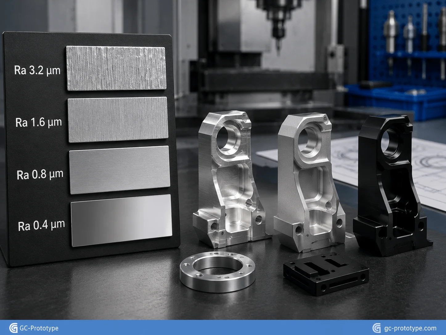
Understanding cnc machining surface roughness ra values helps Product Designers and Manufacturing Engineers specify surfaces that support function without creating unnecessary finishing cost. Ra represents the arithmetic average deviation of the measured surface profile. Lower Ra values indicate smoother surfaces, but the required value should always be linked to function.
An as-machined surface may show visible cutter paths even when dimensions are within tolerance. Tool diameter, feed rate, spindle speed, tool wear, material, cutting direction, machine rigidity, coolant, and finishing strategy all influence the result.
Typical engineering expectations may include:
| Ra Value | Surface Character | Typical Application |
| Ra 3.2 µm | Standard machined finish | General brackets and hidden surfaces |
| Ra 1.6 µm | Controlled production finish | Housings and assembly interfaces |
| Ra 0.8 µm | Fine machined finish | Sliding or sealing-related surfaces |
| Ra 0.4 µm | Very fine finish | Selected bearing, optical, or precision interfaces |
These values are indicative rather than universal guarantees. Geometry, material, measurement direction, and supplier capability must be confirmed. A deep pocket floor may not achieve the same appearance as an open external face, and a turned shaft may reach a smoother finish more economically than a milled surface.
As-machined, bead-blasted, and anodized surfaces should not be treated as visually equivalent:
| Finish | Appearance | Dimensional Impact | Cost Consideration |
| As-machined | Visible tool paths | Minimal secondary change | Lowest finishing cost |
| Bead blasted | Uniform matte | May affect edges and small details | Additional handling |
| Anodized | Colored or natural protective layer | Coating thickness affects fits | Masking and color control add cost |
| Polished | Smooth or reflective | Can remove measurable material | Labor-intensive |
A practical drawing should identify which surfaces are cosmetic, which are functional, and which can remain standard as-machined. Requiring Ra 0.4 µm and premium appearance on every hidden surface increases cost without improving performance.
Financial Breakdown: cnc machining vs 3d printing cost comparison
A useful cnc machining vs 3d printing cost comparison considers quantity, geometry, material, finish, tolerance, and the purpose of the prototype. Three-dimensional printing usually has a lower setup burden and is well suited to complex one-off parts. CNC machining often becomes more attractive when real material properties, tighter tolerances, better surfaces, or repeated low-volume production are required.
For one to five concept models, additive manufacturing may be the faster and cheaper route. For functional parts in aluminum, stainless steel, PEEK, or POM, machining may provide better engineering value even at very low quantity. Between 10 and 500 pieces, optimized fixtures, repeatable toolpaths, and batch purchasing can reduce the CNC unit price significantly.
| Decision Factor | CNC Machining | 3D Printing |
| Material behavior | Production-grade stock | Process- and orientation-dependent |
| Dimensional accuracy | Generally higher and more predictable | Varies by process |
| Surface finish | Smooth and controllable | Often needs post-processing |
| Internal channels | Limited by tool access | Strong advantage |
| Setup cost | Programming and workholding required | Usually lower |
| Unit economics | Improves with stable batches | Depends on build volume and packing |
| Best use | Functional precision parts | Complex rapid-iteration parts |
Procurement teams should compare the complete delivered cost, not only the base manufacturing price. Inspection, finishing, threaded inserts, tapping, painting, heat treatment, scrap, and shipping can change the decision.
Essential DFM Rules for Cost Reduction
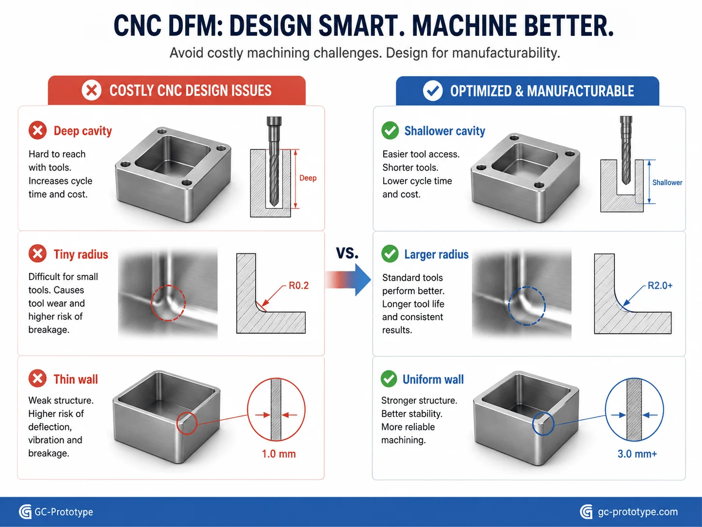
Designing for Machinability: Internal Radii, Wall Thickness, and Deep Cavities
Good CNC DFM reduces machine time, tool wear, setup complexity, deformation, and inspection effort. The strongest cost savings usually come from geometry changes made before manufacturing begins.
Use Practical Internal Radii
Rotating end mills cannot create a perfectly sharp internal corner. The smaller the required radius, the smaller and less rigid the tool must be. Small tools remove material slowly, deflect more easily, and are more likely to break.
Larger internal radii allow the supplier to use stronger cutters and higher material-removal rates. For deep cavities, the corner radius should be generous enough to avoid extremely long, slender tools. A useful design review asks whether the radius is functionally necessary or simply inherited from a visual CAD model.
Control Wall Thickness
Thin walls can vibrate, bend, or move after material is removed. Aluminum walls may tolerate thinner sections than hard steel in some geometries, but support, height, tool access, and residual stress are critical.
Where possible, maintain consistent thickness, avoid isolated flexible tabs, and leave enough material for stable finishing. A thin wall that looks acceptable in the final CAD model may require temporary support structures or staged machining during production.
Avoid Excessively Deep Cavities
Deep pockets require long tools, multiple step-down passes, slower feed rates, and careful chip evacuation. Tool deflection can create taper, chatter, and poor finish. A cavity with a depth many times greater than its width may require specialized cutters or EDM.
Cost can often be reduced by increasing the cavity width, reducing depth, opening one side, splitting the component into an assembly, or allowing larger corner radii.
Standardize Holes and Threads
Standard drill sizes, thread forms, and reamers reduce tooling complexity. Very deep blind threads, unusual pitches, and tiny threaded holes can increase cycle time and inspection requirements.
Reduce Setup Count
Every additional orientation requires handling, workholding, datum transfer, and verification. Features that can be reached from common directions are generally more economical. Five-axis machining can consolidate setups, but the design should still avoid unnecessary side features.
Apply Tight Tolerances Selectively
A tolerance should be justified by function. Tight limits on non-critical dimensions create extra finishing and inspection. Geometric tolerances such as position, flatness, or profile may communicate functional intent more effectively than a collection of unnecessarily tight coordinate dimensions.
| DFM Issue | Manufacturing Impact | Better Design Choice |
| Tiny internal radius | Small fragile tools and slow cutting | Increase radius |
| Deep narrow pocket | Long tools and poor chip removal | Widen, shorten, or split |
| Thin unsupported wall | Chatter and deformation | Increase thickness or add support |
| Custom thread | Special tools and gauges | Use a standard thread |
| Side feature on every face | Multiple setups | Consolidate feature directions |
| Tight tolerance everywhere | Higher finishing and inspection cost | Limit to functional areas |
CNC Machining Cost Structure
CNC quotation cost usually includes raw material, programming, setup, fixtures, machine time, cutting tools, finishing, inspection, packaging, and profit. Understanding these elements helps Engineering Managers and Strategic Buyers identify where changes will create meaningful savings.
Material cost depends on grade, stock size, availability, and waste. Oversized stock increases both purchase price and cutting time. Programming and setup are largely non-recurring expenses, so unit price normally decreases as quantity rises.
Cycle time is often the largest recurring cost. Complex toolpaths, deep pockets, frequent tool changes, and tight finishes extend machine occupancy. Secondary operations such as heat treatment, anodizing, polishing, welding, or laser marking add both cost and scheduling risk.
| Cost Driver | Why It Matters | Optimization Strategy |
| Material and stock size | Premium alloys and excess stock increase waste | Select near-net standard stock |
| Programming | Complex toolpaths require engineering time | Stabilize CAD before release |
| Setup count | Each orientation requires handling | Consolidate features |
| Cycle time | Machine occupancy drives recurring cost | Simplify geometry |
| Tool wear | Hard or abrasive materials consume cutters | Avoid over-specified materials |
| Tolerances | Tight limits require finishing and inspection | Prioritize critical features |
| Surface finish | Fine finishes require extra passes | Specify only where necessary |
| Quantity | Setup cost is distributed across the batch | Combine stable demand |
For prototype quantities, programming and setup may dominate. For 50–500 pieces, dedicated soft jaws, pallet systems, in-process probing, and batch inspection can improve unit economics. The supplier should separate one-time and recurring costs where possible.
Application Scenarios
Aerospace Structural Housing
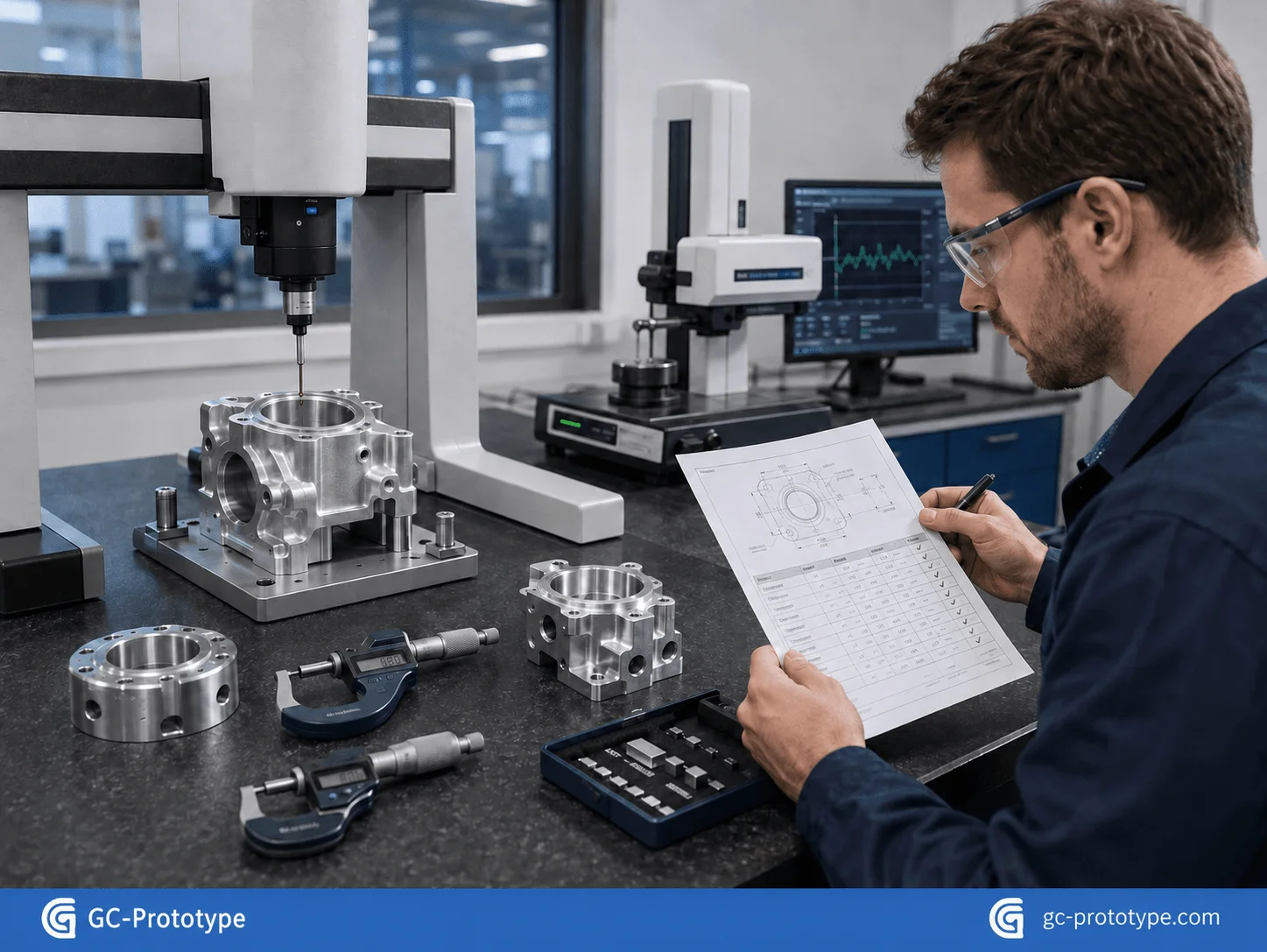
An aerospace team requires a 7075-T6 housing with angled bores, thin walls, and weight-reduction pockets. Five-axis machining reduces setup transfers, while critical bores and mounting faces receive detailed CMM inspection.
Medical Diagnostic Component
A medical-device company needs a stainless steel or PEEK component with cleanable surfaces, controlled fits, and documented material. General dimensions follow the drawing standard, while sealing and alignment features receive explicit tolerances.
Robotic Joint and Actuator Mount
A robotics manufacturer uses CNC machining for bearing seats, motor interfaces, and lightweight structural geometry. Coaxial features are completed from a common datum to reduce assembly error.
Consumer Electronics Prototype
A hardware team machines aluminum and engineering-plastic housings to validate connector placement, thermal behavior, assembly, and premium surface finish before tooling.
Automotive Test Fixture
An automotive supplier needs durable fixtures and sensor mounts for validation. Machining supports rapid revision, robust materials, and low-volume production without dedicated molds.
Industrial Automation Replacement Part
A factory needs a discontinued bracket or shaft. Reverse engineering and CNC machining provide a practical replacement without rebuilding legacy tooling.
Selecting a CNC Machining Supplier
A capable supplier should provide DFM review, three-axis and five-axis milling, turning, engineering-plastic machining, surface finishing, dimensional inspection, and revision management.
The RFQ package should include:
STEP or native 3D CAD files
Dimensioned 2D drawings
Material grade and condition
Required quantity
General tolerance standard
Critical dimensions and GD&T
Surface roughness requirements
Heat treatment or coating
Cosmetic surface classifications
Inspection documentation
Delivery target
A strong supplier should identify inaccessible features, unrealistic tolerances, fragile walls, expensive finishes, and setup risks before machining begins. It should also explain which dimensions can be held as-machined and which may require grinding, honing, reaming, or other secondary operations.
Frequently Asked Questions
What Is CNC Machining Best Used For?
CNC machining is best suited to functional prototypes, precision components, low-volume production, fixtures, replacement parts, and products requiring engineering-grade metals or plastics.
When Should Five-Axis Machining Be Used?
Use five-axis machining when the part contains multi-face features, complex contours, angled bores, or relationships that would otherwise require several setups.
What Does ISO 2768 Mean on a Drawing?
ISO 2768 provides general tolerances for dimensions and geometrical features that do not have individual tolerance callouts. Critical dimensions still require explicit limits.
Can CNC Machining Achieve ±0.005 mm?
Selected features may achieve this under suitable conditions, but capability depends on geometry, material, temperature, machine stability, workholding, and inspection method.
Which Ra Value Is Suitable for a Standard Machined Part?
Ra 3.2 or Ra 1.6 µm is common for many general surfaces. Seals, bearings, or sliding interfaces may require Ra 0.8 or Ra 0.4 µm.
Is CNC Machining Cheaper Than 3D Printing?
It depends on geometry, material, quantity, and required finish. CNC often provides better value for simple precision parts in production materials, while printing is stronger for complex one-off geometry.
How Can CNC Machining Cost Be Reduced?
Increase internal radii, avoid deep narrow cavities, use practical wall thickness, reduce setups, standardize holes and threads, and limit tight tolerances to functional features.
What Files Are Needed for a CNC Quote?
Provide a solid 3D model, dimensioned drawing, material, quantity, tolerance standard, critical dimensions, finish, inspection requirements, and delivery target.
CNC machining provides a reliable path from engineering concept to production-quality metal and plastic components. Its value comes from real materials, tight dimensional control, rapid design changes, broad finishing options, and scalable low-volume manufacturing without dedicated mold tooling.
The most successful projects combine five-axis capability where justified, sensible ISO 2768 general tolerances, function-based surface specifications, and practical DFM. Larger internal radii, stable wall thickness, accessible cavities, standard threads, fewer setups, and clearly prioritized critical dimensions can substantially reduce cost and lead time.
Transitioning your complex engineering concepts into high-precision CNC-machined parts should not compromise your product budget or launch schedule. Whether you are a Senior Mechanical Engineer finalizing critical aerospace housings or a Sourcing Manager looking to balance cnc machining vs 3d printing cost comparison, GC Prototype is your trusted manufacturing partner.
Our capabilities include three-axis and five-axis milling, CNC turning, metal and engineering-plastic machining, surface finishing, CMM inspection, rapid prototyping, and low-volume production.