Address:
Shenzhen Bao'an District Xinqiao Subdistrict Huangpu Community Huangpu East Ring Road No. 504 Shenzhen Yuan Industrial City Building C
Work Hours:
Monday to Friday: 9AM - 21PM
Weekend: 9AM - 21PM

Address:
Shenzhen Bao'an District Xinqiao Subdistrict Huangpu Community Huangpu East Ring Road No. 504 Shenzhen Yuan Industrial City Building C
Work Hours:
Monday to Friday: 9AM - 21PM
Weekend: 9AM - 21PM

Injection molding is the dominant production process for manufacturing repeatable plastic components at commercial scale. When a product moves beyond 3D-printed prototypes, vacuum-cast samples, and pilot builds, molding provides the output, dimensional consistency, surface quality, and material performance required for mass production. For Senior Mechanical Engineers, Product Designers, NPI Managers, and Procurement Professionals, however, success depends on much more than buying a mold. Part geometry, resin behavior, shrinkage, draft, wall thickness, gate location, tooling strategy, quality documentation, and lifetime volume all influence cost and risk.
This guide explains how to plan medical and consumer-electronics parts, compare injection molding with additive manufacturing, estimate tooling economics, control polycarbonate shrinkage, apply practical DFM rules, and select a qualified supplier for global B2B programs.
How Injection Molding Supports the Transition to Mass Production
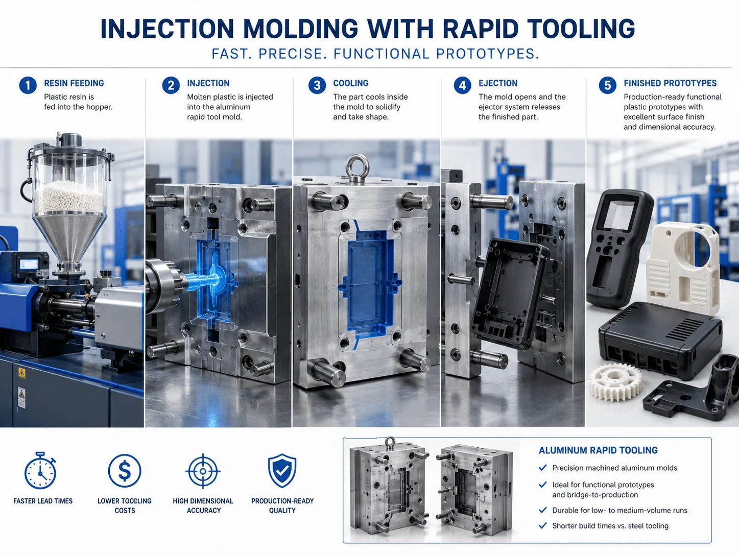
Injection molding converts thermoplastic pellets into finished components through a controlled cycle. The resin is dried when required, melted inside a heated barrel, injected into a precision metal mold, packed under pressure, cooled, and ejected. Gates, runners, and flash are then removed before inspection, finishing, or assembly.
The process requires a larger upfront investment than 3D printing or silicone molding, but the economic model changes once quantity increases. A well-designed mold can produce thousands or millions of parts with short cycle times and highly repeatable geometry. Multi-cavity tooling can further increase output by producing several components during each machine cycle.
A typical production program includes:
1.CAD and DFM review
2.Resin and color selection
3.Mold-flow analysis where appropriate
4.Tool design and steel selection
5.Mold manufacturing and assembly
6.T0 and T1 sampling
7.Dimensional and cosmetic correction
8.Process validation and first-article approval
9.Pilot production
10.Full-volume manufacturing and mold maintenance
The production team must evaluate the molded part as part of a complete system. Resin moisture, barrel temperature, mold temperature, injection speed, packing pressure, cooling time, and ejection conditions can all affect dimensions and appearance. A robust product therefore requires alignment between design engineering, tooling, processing, quality, and purchasing.
| Manufacturing Method | Upfront Cost | Unit Cost at Scale | Design Flexibility | Best Use |
| 3D printing | Low | Moderate to high | Very high | Concepts and low quantities |
| Vacuum casting | Moderate | Moderate | Medium | Production-like batches of 10–100 |
| CNC machining | Low | High for complex plastic parts | High | Precision prototypes |
| Injection molding | High | Very low at scale | Low after tool approval | Stable repeat production |
Industry Applications & Material Compliance
Medical Hardware Excellence: Following an injection molding design guide for medical devices
A practical injection molding design guide for medical devices begins by defining the part’s intended use, contact conditions, cleaning method, sterilization environment, mechanical function, and regulatory documentation. A handheld diagnostic housing, surgical instrument handle, fluid connector, laboratory cartridge, and implantable component do not share the same risk profile.
Medical-device manufacturers may require biocompatibility data, lot traceability, controlled material handling, validated cleaning, and production in a controlled or cleanroom environment. References to FDA requirements or ISO 10993 should be tied to the actual device classification, contact duration, and approved material grade. A generic statement that a resin is “medical grade” is not sufficient without supporting documentation relevant to the application.
Common resin families for medical equipment include polycarbonate, ABS, PC/ABS, polypropylene, POM, nylon, TPE, and selected high-performance polymers. The final choice depends on impact resistance, chemical exposure, clarity, dimensional stability, sterilization, friction, and cost.
Medical DFM should focus on cleanability and process stability. Uniform wall thickness reduces sink and differential cooling. Smooth internal transitions reduce stress concentrations and areas where contamination may collect. Draft improves ejection and reduces cosmetic drag marks. Rounded corners support both molding and cleaning.
For housings that must withstand repeated disinfectant exposure, the material supplier should confirm resistance to the exact chemicals used in practice. Polycarbonate, for example, provides clarity and impact strength but can be vulnerable to stress cracking when exposed to incompatible cleaners or molded with excessive residual stress.
Critical design questions include:
Does the part contact skin, tissue, fluid, or only internal equipment?
Is sterilization required, and by which method?
Are there transparent windows, optical paths, or fluid channels?
Which dimensions affect sealing, alignment, or dosage?
Are weld lines acceptable near load-bearing or fluid-contact features?
Is cleanroom molding required?
What traceability and inspection records are needed?
Can the resin and colorant be maintained throughout the product life?
Medical housings frequently use snap fits, threaded inserts, seals, and overmolded grips. These features should be validated using production-intent samples because prototype materials may behave differently from the final molded resin.

Consumer Electronics and Smart Hardware: custom injection molding for consumer electronics
Professional custom injection molding for consumer electronics supports thin-wall housings, battery compartments, bezels, internal frames, buttons, light guides, connector surrounds, and wearable-device components. These products combine demanding cosmetic expectations with aggressive packaging constraints and high annual volumes.
A premium electronics enclosure must control gloss, texture, color, flow marks, weld lines, gate vestige, sink, and panel-gap consistency. Material options often include ABS for cost-effective housings, polycarbonate for impact resistance and transparency, PC/ABS for balanced toughness and processing, and TPE for grips, seals, and soft-touch features.
Thin-wall molding can reduce weight and material consumption, but it narrows the process window. The resin must flow through the cavity before freezing, and the mold needs effective venting, balanced gates, and controlled cooling. Excessively thin walls may require higher injection pressure, faster filling, specialized machines, or a more flowable material grade.
Surface finish should be defined using an approved standard, such as a physical texture plaque or mold-finish specification. A matte texture can hide minor visual variation, while a high-gloss surface exposes sink, flow, and polishing defects. Draft must increase as texture becomes deeper because the molded surface mechanically engages with the cavity texture during ejection.
For smart hardware, electronics integration should be reviewed before tooling. PCB standoffs, antenna zones, light pipes, buttons, speakers, connector openings, heat sources, grounding features, and assembly tools all influence the molded geometry. A housing that looks correct externally can still fail if internal ribs block cables or if a screw boss creates sink on a Class-A surface.
Engineering Precision & Process Trade-Offs
Material Behavior: Calculating injection molding shrinkage rate for polycarbonate
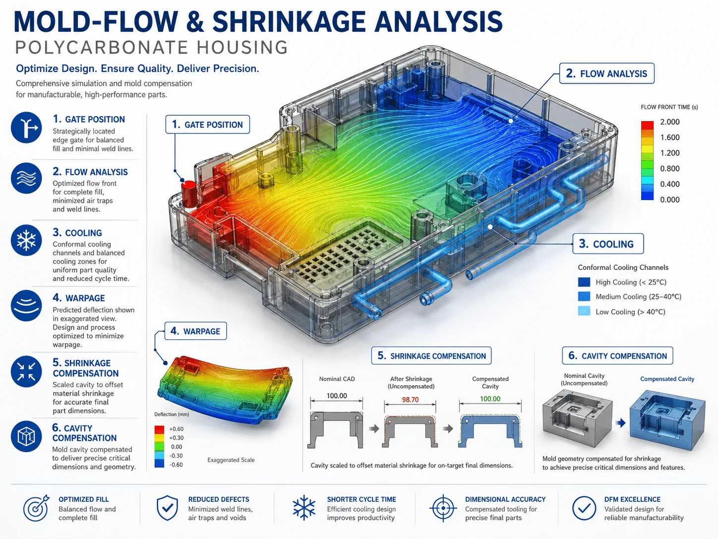
The injection molding shrinkage rate for polycarbonate is an important starting point for tool design, but it should never be treated as one fixed universal percentage. Actual shrinkage depends on the exact resin grade, filler content, melt temperature, mold temperature, packing pressure, gate location, wall thickness, flow direction, and cooling conditions.
Polycarbonate is generally an amorphous polymer, so its shrinkage is often lower and more predictable than that of many semi-crystalline plastics. Even so, a nominal material-data-sheet value cannot replace process-specific tool compensation.
A simplified tooling calculation may use:
Mold dimension = target part dimension ÷ (1 − expected shrinkage)
This formula provides an initial estimate, not a final guarantee. If a target dimension is 100 mm and the assumed linear shrinkage is 0.6%, the cavity would begin near 100.60 mm before considering local geometry, steel-safe strategy, process tuning, and measured sampling results.
Engineers should expect direction-dependent behavior. Flow orientation, glass-fiber reinforcement, rib layout, and gate position can produce different shrinkage along different axes. Differential cooling can also cause warpage even when average shrinkage appears correct.
A robust approach includes:
Reviewing the resin supplier’s current technical data
Using mold-flow simulation for complex or high-risk parts
Identifying critical datums and dimensions
Applying steel-safe conditions where practical
Planning adjustment stock in inserts
Measuring production-intent samples after conditioning
Separating dimensional correction from cosmetic correction
Recording the approved processing window
| Shrinkage Influence | Potential Effect | Engineering Response |
| Wall-thickness variation | Sink and differential shrinkage | Maintain uniform sections |
| Gate position | Directional flow and packing differences | Balance fill and locate gates strategically |
| Mold temperature | Changes cooling and residual stress | Validate a stable process window |
| Glass fiber | Directional shrinkage and warpage | Simulate fiber orientation |
| Inadequate packing | Excess shrinkage and voids | Optimize gate size and holding pressure |
| Uneven cooling | Warpage and dimensional drift | Balance cooling channels |
Critical features such as snap fits, optical windows, screw-boss patterns, sealing surfaces, and PCB interfaces should not rely solely on nominal shrinkage. They should be checked during T0, T1, and pilot builds and adjusted through controlled tooling changes.
Cost Breakdown: plastic injection molding vs 3d printing cost
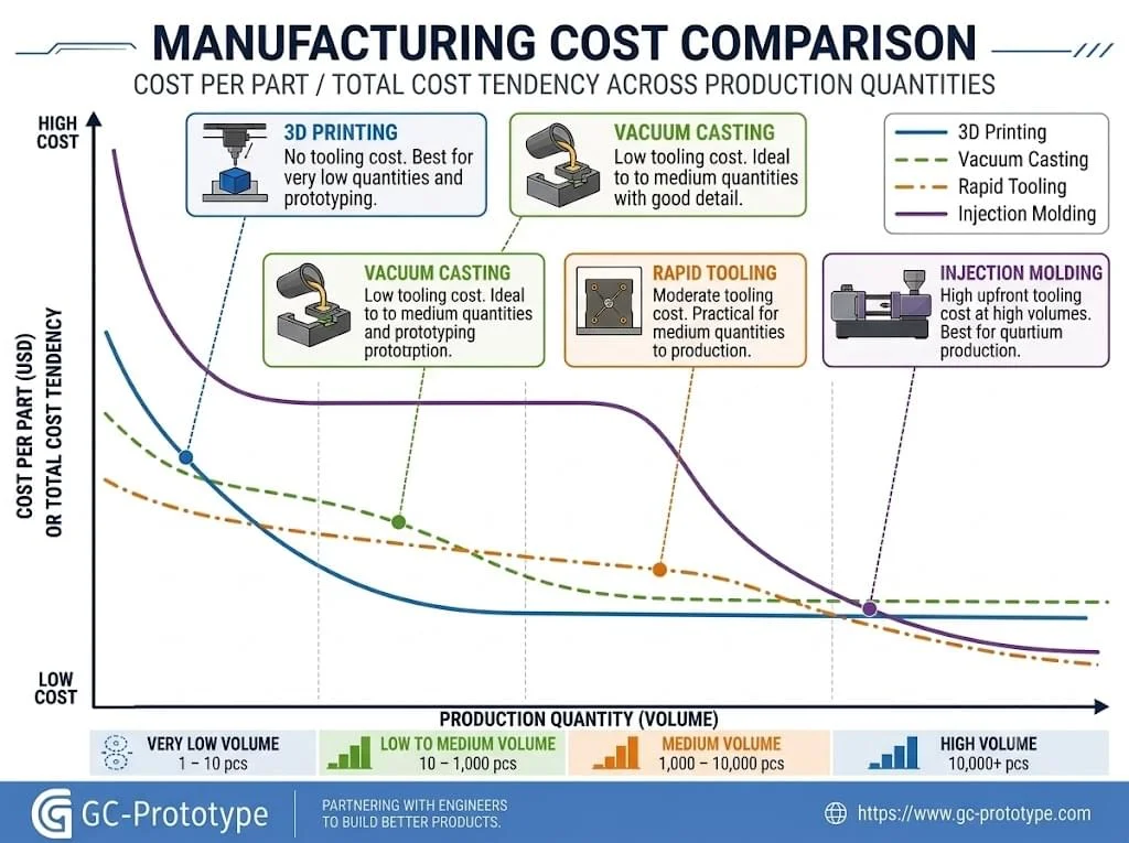
The plastic injection molding vs 3d printing cost comparison depends on quantity, geometry, material, finish, tolerance, and product life. Three-dimensional printing requires little or no tooling, making it ideal for early prototypes and frequent design changes. Injection molding requires a tool, but recurring cost can drop dramatically after the tool is approved.
For one to ten parts, printing is usually more economical. Between tens and hundreds of parts, the answer depends on component size, required finish, material performance, and whether bridge methods such as vacuum casting are suitable. Once stable demand reaches the thousands, molding often delivers the lowest total cost per unit.
| Cost Factor | 3D Printing | Injection Molding |
| Tooling | Minimal | Significant upfront investment |
| Design changes | Immediate from updated CAD | Tool modifications may be required |
| Unit cost at low volume | Usually favorable | High due to amortization |
| Unit cost at high volume | Relatively high | Usually much lower |
| Material behavior | Process-dependent | Production resin performance |
| Surface consistency | Depends on process and finishing | High with a stable mold and process |
| Production speed | Build-time dependent | Short repeatable cycles |
| Best economic use | Prototypes and customized parts | Stable mass production |
Total cost of ownership should include more than tool price and molded unit cost. Procurement teams should compare mold design and manufacturing, sampling, resin, cycle time, machine tonnage, scrap rate, secondary machining, inserts, finishing, inspection, packaging, freight, maintenance, storage, and expected lifetime volume.
A lower-cost mold may become expensive if it produces long cycles, inconsistent dimensions, frequent flash, or early wear. Conversely, a highly complex production tool may be unnecessary for a product with uncertain demand. The financial decision should be based on a credible forecast, expected revisions, and program duration.
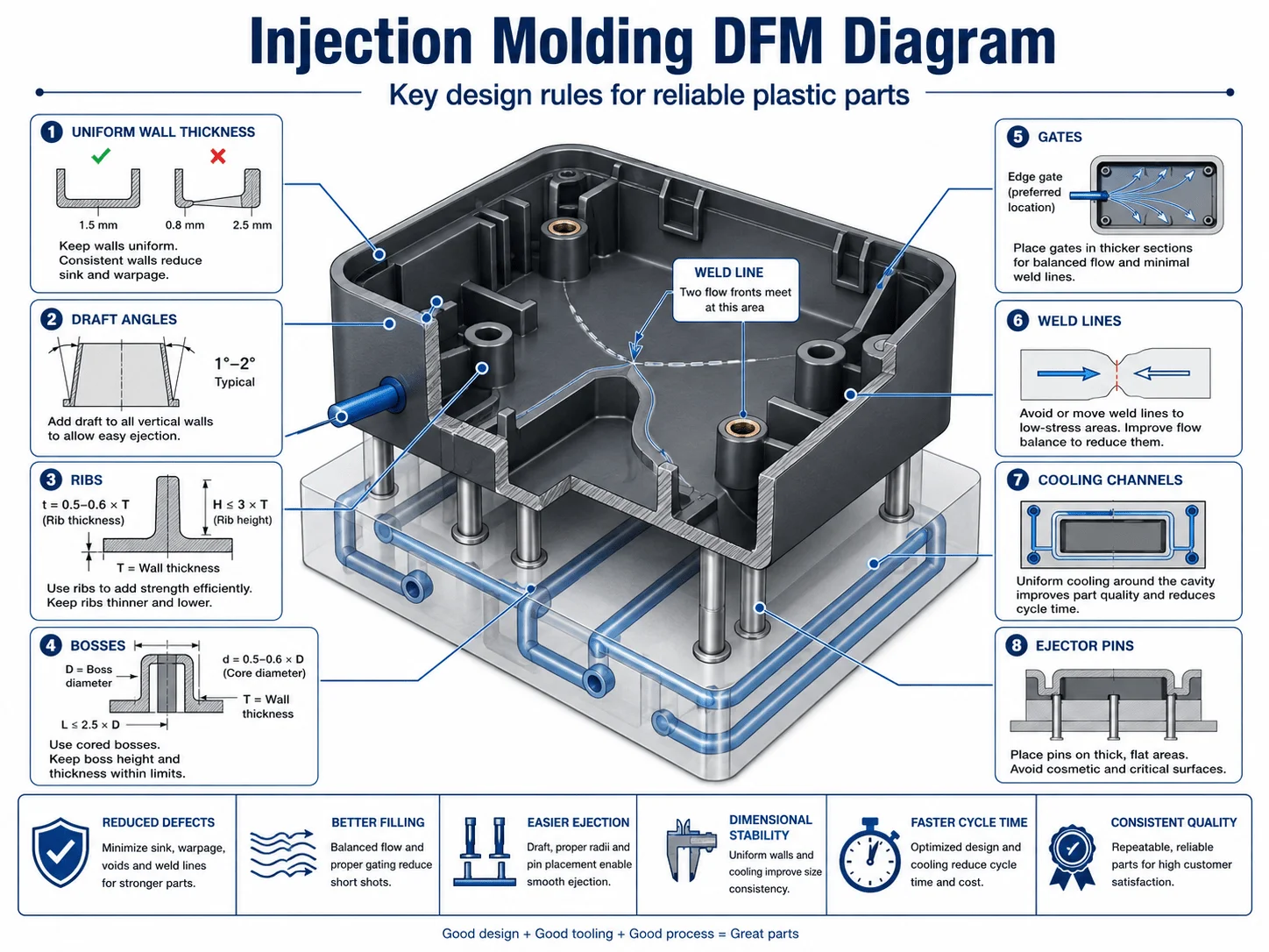
Essential DFM Rules & Supplier Selection
Critical DFM Rules for Cost Reduction: Draft Angles, Ribs, and Wall Thickness
Injection-molding DFM should begin before the industrial design is frozen. Early collaboration reduces tooling complexity, prevents repeated mold modifications, and shortens the route to production approval.
Maintain Uniform Wall Thickness
Consistent wall thickness supports balanced filling, packing, cooling, and shrinkage. Thick isolated sections cool slowly and may create sink, internal voids, or warpage. Instead of making a region solid, use ribs, gussets, and cored bosses. Where thickness must change, use gradual transitions rather than abrupt steps.
Add Appropriate Draft
Draft allows the part to release from the tool without excessive friction, scraping, or ejector force. Smooth surfaces may need modest draft, while deep textures require more. Internal features often need additional attention because the plastic shrinks onto the core during cooling.
Zero-draft walls should be reserved for short functional zones and reviewed with the moldmaker. Slides, lifters, or collapsible cores can solve some undercuts, but they increase tooling cost and maintenance.
Design Ribs and Bosses Carefully
Ribs improve stiffness without adding excessive mass, but overly thick ribs can create visible sink on the opposite surface. A common DFM approach is to make rib thickness a fraction of the adjacent wall, then confirm the exact ratio with the resin, geometry, and cosmetic requirement.
Bosses should be supported with ribs or gussets rather than connected by heavy solid sections. Screw-boss diameter, pilot hole, thread engagement, and insert method should be matched to the selected fastener.
Use Practical Corner Radii
Sharp internal corners concentrate stress and impede flow. Rounded internal and external transitions improve filling, structural performance, and mold durability. Corners should maintain consistent wall thickness rather than creating hidden heavy sections.
Plan Gates and Weld Lines
Gate type and position influence filling, packing, shrinkage, weld lines, and gate vestige. Gates should not be placed solely for tool convenience. They must support balanced flow and keep visible marks away from Class-A surfaces.
Weld lines form where flow fronts meet. Their location matters near snap fits, screw bosses, pressure features, and transparent surfaces. Simulation and tool design can move or strengthen these regions through gate changes, venting, temperature control, or geometry modification.
Design for Ejection
Ejector pins need stable surfaces that can withstand force without distortion. Thin cosmetic walls, textured surfaces, and deep cores increase ejection risk. Ejector marks should be located on hidden or non-critical surfaces.
Minimize Unnecessary Side Actions
Side holes, hooks, windows, and undercuts may require slides or lifters. These mechanisms increase tool size, lead time, maintenance, and risk. Reorienting a feature, using an assembly, or adding a secondary operation may be more economical.
| DFM Problem | Likely Defect or Cost | Preferred Design Response |
| Thick boss connected to thin wall | Sink and voids | Core the boss and add ribs |
| No draft on textured wall | Drag marks and ejection damage | Increase draft |
| Sharp internal corner | Stress concentration and poor flow | Add radius |
| Gate near cosmetic face | Visible vestige and flow variation | Relocate or use a different gate |
| Multiple side undercuts | Complex expensive tooling | Simplify or split the assembly |
| Tight tolerance on every feature | Excessive tool correction and inspection | Prioritize critical dimensions |
Mold Cost, Tooling Strategy & Production Economics
Mold cost varies because a tool can range from a simple single-cavity aluminum insert to a hardened multi-cavity system with slides, lifters, hot runners, sensors, automated unscrewing, and interchangeable inserts. Major cost drivers include part size, projected area, cavity count, tool steel, mold base, side actions, runner design, polish, tolerance, cooling, and expected tool life.
| Tooling Type | Upfront Cost | Expected Use | Main Advantage |
| Soft prototype tool | Low | Samples and limited runs | Fast and economical |
| Aluminum rapid tool | Moderate | Pilot and bridge production | Short lead time |
| Pre-hardened steel tool | Medium to high | Medium-volume production | Improved durability |
| Hardened production tool | High | Long-term mass production | Maximum life and stability |
The least expensive tool is not always the lowest-cost solution. Poor cooling can extend every cycle, while inadequate venting can create burns, short shots, and scrap.
A transparent quotation should separate mold cost, samples, resin, molding, secondary operations, inspection, packaging, and maintenance assumptions. Tool ownership, storage, preventive maintenance, engineering changes, and end-of-life handling should also be documented.
Application Scenarios
Medical Diagnostic Enclosure
A medical manufacturer needs a PC/ABS housing with cleanable surfaces, impact resistance, threaded inserts, and traceable resin. Uniform walls and controlled bosses reduce sink, while a documented molding process supports repeat production.
Consumer Electronics Housing
A smart-device company requires a thin-wall enclosure with fine texture, tight connector alignment, and consistent color. Mold-flow analysis helps position gates and manage weld lines away from visible surfaces.
Automotive Sensor Body
An automotive supplier produces a glass-filled nylon housing with sealing grooves and metal inserts. Fiber orientation, shrinkage, and warpage are reviewed before tooling.
Robotic Controller Cover
A robotics company consolidates several fabricated covers into one molded PC/ABS component. Internal ribs add stiffness, while snap fits reduce assembly labor.
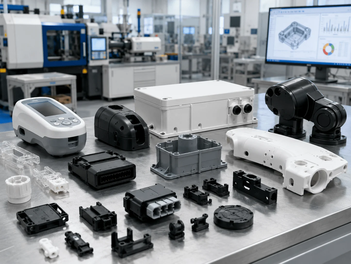
Selecting an Injection Molding Supplier
A qualified supplier should support material selection, detailed DFM, mold-flow analysis, prototype and production tooling, process development, molding trials, inspection, insert molding, overmolding, assembly, finishing, traceability, maintenance, and revision control.
The RFQ package should include STEP files, dimensioned drawings, material grade, annual quantity, lifetime demand, cosmetic standards, critical dimensions, color, texture, inserts, compliance documentation, and delivery expectations.
A capable supplier should identify wall-thickness risks, draft limitations, gate location, expected weld lines, sink risk, undercuts, shrinkage assumptions, and the recommended tooling strategy before cutting steel.
Frequently Asked Questions
When should a project move from 3D printing to injection molding?
Move toward molding when the design is stable, demand is recurring, production material performance is required, and tooling can be amortized across a credible volume.
What wall thickness is best?
The ideal wall depends on resin, flow length, part size, function, and cosmetic requirements. Uniformity is usually more important than one universal value.
Can injection molding achieve tight tolerances?
Yes, but capability depends on resin, shrinkage, geometry, tool construction, process control, and measurement. Tight limits should be applied only to functional features.
What causes sink marks?
Sink commonly results from thick sections, oversized ribs or bosses, inadequate packing, or uneven cooling.
What is the difference between insert molding and overmolding?
Insert molding surrounds a pre-positioned component such as a metal insert. Overmolding adds a second material over a molded substrate for grips, seals, or multi-material functions.
How can mold cost be reduced?
Simplify undercuts, reduce side actions, use practical tolerances, standardize inserts, and freeze critical geometry before tool manufacture.
Injection molding is the key manufacturing process for converting validated plastic designs into repeatable commercial products. Its economic advantage comes from rapid cycles, stable quality, production-grade materials, multi-cavity output, and low recurring unit cost.
The strongest programs combine practical DFM, accurate shrinkage planning, suitable materials, balanced gates, efficient cooling, realistic tolerances, and a tooling strategy matched to lifetime demand.
Scaling your plastic hardware from functional prototype to high-volume market deployment requires precision engineering and smart tooling investment. Whether you are a Senior Mechanical Engineer finalizing medical-grade enclosures or a Sourcing Manager evaluating plastic injection molding vs 3d printing cost, GC Prototype is your expert manufacturing partner.