Address:
Shenzhen Bao'an District Xinqiao Subdistrict Huangpu Community Huangpu East Ring Road No. 504 Shenzhen Yuan Industrial City Building C
Work Hours:
Monday to Friday: 9AM - 21PM
Weekend: 9AM - 21PM

Address:
Shenzhen Bao'an District Xinqiao Subdistrict Huangpu Community Huangpu East Ring Road No. 504 Shenzhen Yuan Industrial City Building C
Work Hours:
Monday to Friday: 9AM - 21PM
Weekend: 9AM - 21PM

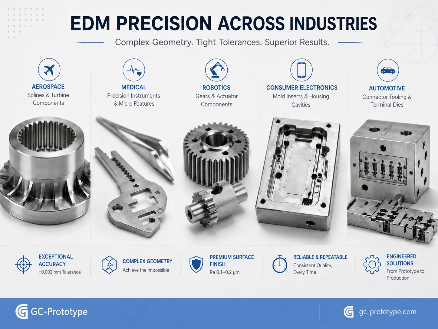
EDM surface treatment plays a critical role when hardened tool steel, carbide, deep mold cavities, sharp internal details, or micro-scale features cannot be machined efficiently with conventional cutting tools. Electrical discharge machining removes conductive material through controlled electrical sparks rather than direct mechanical contact, making it especially valuable for precision molds, aerospace components, medical hardware, robotics parts, and high-performance industrial tooling. For Senior Mechanical Engineers, Manufacturing Engineers, Process Engineers, and Sourcing Managers, the challenge is not simply achieving the required geometry. The real challenge is defining the correct texture standard, controlling surface integrity, removing the recast layer, balancing roughness against cycle time, and selecting a supplier capable of repeatable inspection.
This guide explains VDI 3400 texture control, wire EDM Ra values, recast-layer removal, mirror EDM, manual polishing economics, DFM rules, application scenarios, quality assurance, and supplier selection for demanding B2B projects.
How EDM Creates and Modifies a Surface
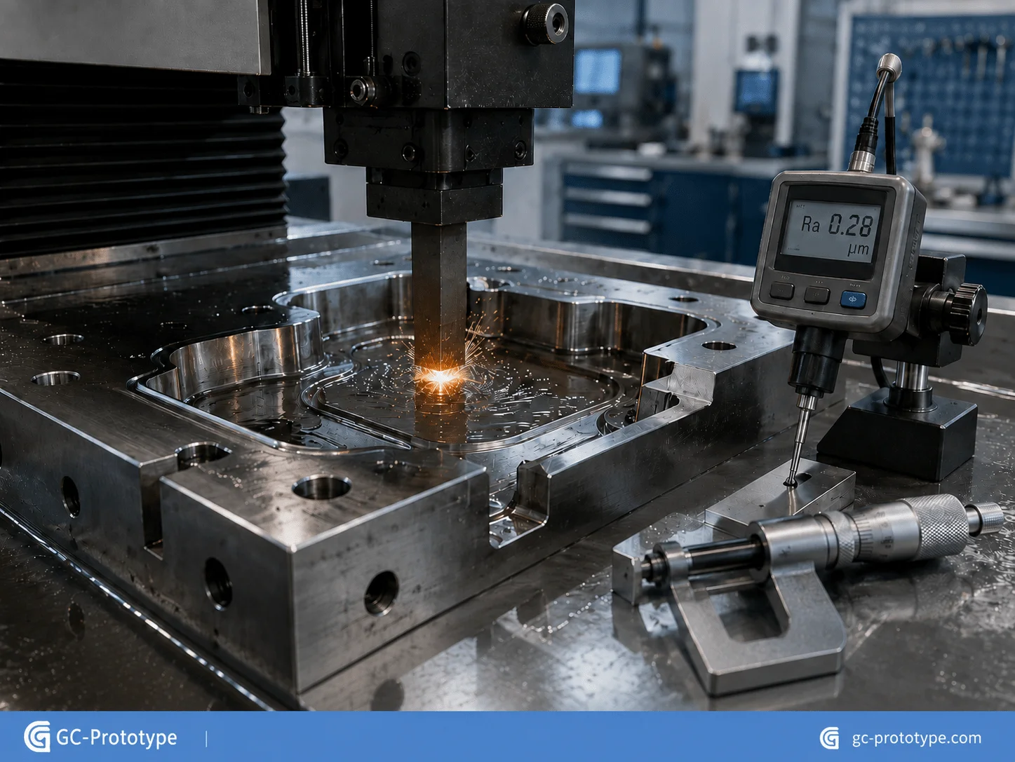
EDM is a non-contact thermal machining process. A shaped electrode or moving wire is separated from the conductive workpiece by a small dielectric gap. Repeated electrical discharges generate localized heat, melting and vaporizing microscopic amounts of material. The dielectric fluid cools the surface and flushes away debris.
Sinker EDM uses graphite, copper, or copper-tungsten electrodes to reproduce cavities, ribs, slots, logos, and internal forms. Wire EDM uses a continuously moving wire to cut precision through-profiles, punches, dies, splines, gears, and narrow slots. Both methods can machine extremely hard conductive materials without applying conventional cutting force.
The final surface depends on pulse energy, pulse duration, electrode material, discharge gap, flushing, dielectric condition, machine stability, and the number of finishing passes. Roughing parameters remove material quickly but leave deeper craters and a thicker thermally affected layer. Finishing parameters use lower energy to improve roughness and dimensional control, although cycle time increases.
| EDM Process | Best Application | Main Surface-Control Factor |
| Sinker EDM | Blind cavities, deep ribs, mold details | Electrode finish, orbiting, flushing |
| Wire EDM | Through-profiles and precision contours | Number of skim passes and wire technology |
| Micro EDM | Micro-holes and miniature features | Electrode wear and debris evacuation |
| Mirror EDM | Fine mold cavities and high-gloss tooling | Low-energy finishing and dielectric stability |
Industry Standards & Surface Specifications
Standardizing Texture: Mastering the edm surface finish vdi 3400 standard
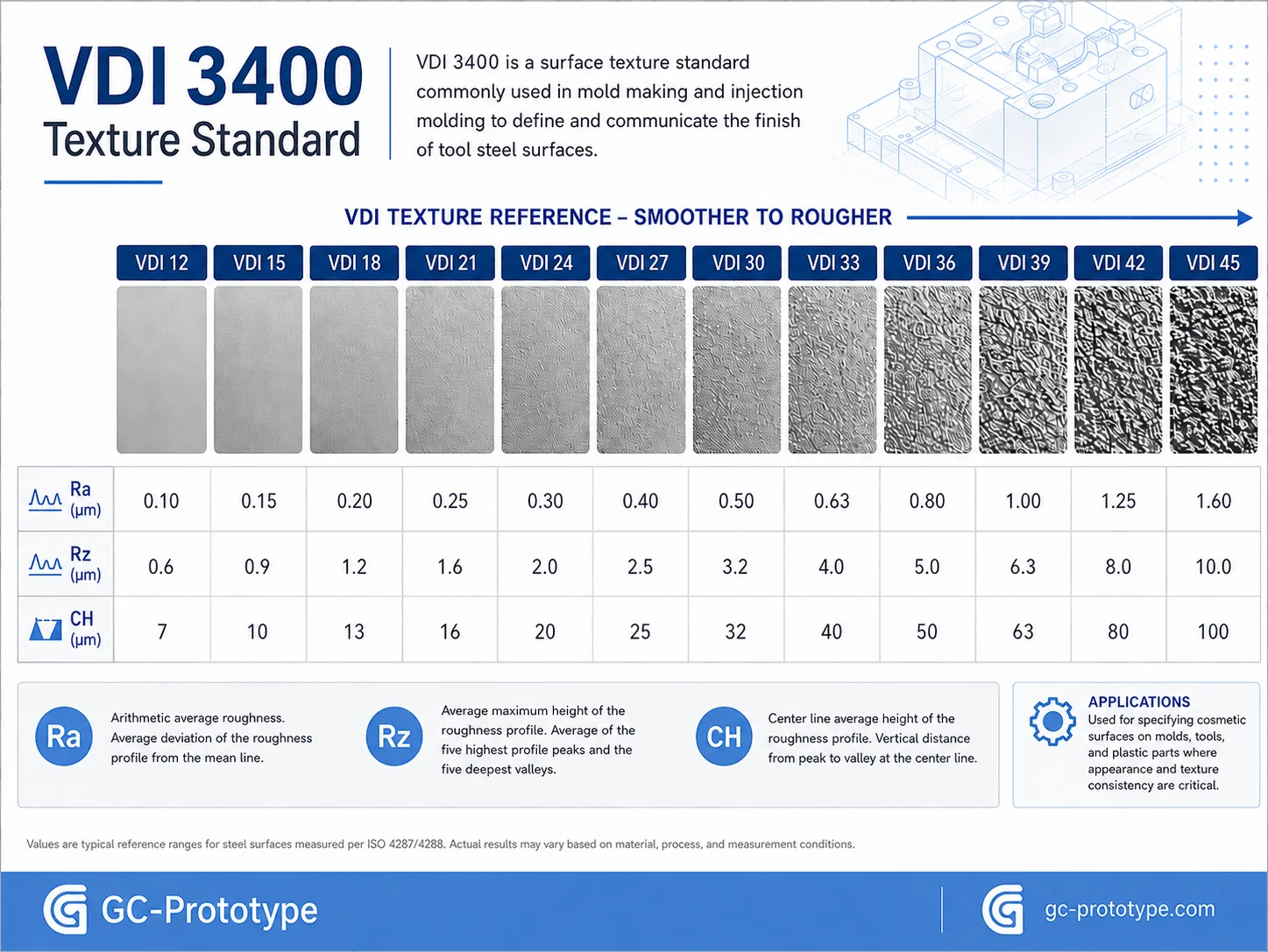
The edm surface finish vdi 3400 standard gives moldmakers, Mechanical Engineers, and Industrial Designers a common reference for spark-eroded textures. It is widely used to communicate the desired appearance and roughness of injection mold cavities, die-casting tools, and precision tooling surfaces.
VDI grades commonly referenced in commercial texture charts range from VDI 12 to VDI 45. Lower values represent finer matte surfaces, while higher values represent progressively coarser textures. The exact Ra and Rz relationship may vary slightly between reference charts and measurement conditions, so physical comparison plaques remain important for visual approval.
| VDI Grade | Approximate Ra | Surface Appearance | Typical Application |
| VDI 12 | 0.40 µm | Fine satin | Premium electronics details |
| VDI 15 | 0.56 µm | Fine matte | Medical housings and buttons |
| VDI 18 | 0.80 µm | Soft matte | Laboratory and consumer products |
| VDI 21 | 1.12 µm | General matte | Electronic enclosures |
| VDI 24 | 1.60 µm | Medium texture | Industrial control housings |
| VDI 27 | 2.24 µm | Noticeable grain | Tool grips and automotive trim |
| VDI 30 | 3.15 µm | Coarse matte | Rugged equipment panels |
| VDI 33 | 4.50 µm | Coarse texture | Industrial covers |
| VDI 36 | 6.30 µm | Rough grain | Anti-slip surfaces |
| VDI 39–45 | 9.00–18.00 µm | Heavy texture | Specialized functional surfaces |
A VDI number should not be the only surface specification. A complete drawing should identify the exact textured area, acceptable visual variation, gloss expectation, polymer, color, draft angle, and whether a physical plaque or molded sample controls approval.
For medical equipment and consumer electronics, fine EDM textures can create a controlled matte appearance that reduces glare and hides small visual inconsistencies. In smart hardware and industrial controls, medium or coarse textures can improve grip and make surfaces more resistant to visible scratching.
Deeper textures generally require greater mold-release draft because the molded plastic must disengage from microscopic peaks and valleys. A texture that looks attractive on a flat sample may cause drag marks on a deep vertical wall if the draft is insufficient.
EDM spark texture can also replace a separate chemical etching step in selected applications. This may reduce handoffs, shorten lead time, and avoid some variability associated with transferring the mold to a third-party texturing supplier. However, complex decorative grains and branded leather patterns may still require specialized etching or laser texturing.
Converting Between VDI, Ra, Rz, and CH Scales
Ra is the arithmetic average roughness and is widely used for engineering drawings. Rz reflects the average peak-to-valley height over defined sampling lengths, while CH values appear on some commercial texture charts. These values are related but not interchangeable.
A drawing should specify the required parameter, cutoff, sampling length, direction, and measurement location. Otherwise, two suppliers may report different results while both believe they met the requirement. For cosmetic surfaces, profilometer data should be combined with visual inspection under controlled lighting.
Precision Engineering: Optimizing wire edm surface roughness ra values
Optimizing wire edm surface roughness ra values requires a planned sequence of rough cutting and skim passes. The first cut removes material efficiently and establishes the general profile. Subsequent low-energy passes refine the surface, correct taper, and improve dimensional accuracy.
Indicative industrial results may follow this general pattern:
| Cutting Strategy | Indicative Ra Range | Typical Use |
| One rough cut | Ra 2.0–4.0 µm | Fast blank separation |
| Rough cut plus one skim | Ra 1.0–2.0 µm | General tool components |
| Rough cut plus two skims | Ra 0.5–1.0 µm | Precision profiles |
| Multiple finishing skims | Ra 0.2–0.5 µm | Aerospace and mold components |
| Specialized fine-finish setup | Ra 0.1–0.2 µm or lower | Selected high-end applications |
These values are not universal guarantees. Workpiece thickness, alloy, heat treatment, wire diameter, wire coating, dielectric, flushing, machine condition, and programmed technology all influence the achievable result.
For aerospace splines, precision punches, automation components, and medical hardware, roughness is only one part of the requirement. Taper, straightness, corner accuracy, recast-layer thickness, and fatigue performance may be more important than a very low Ra value.
A buyer should also distinguish between water-dielectric and oil-dielectric systems. Oil-based fine-wire EDM can support very fine surfaces and reduced oxidation in selected applications, but it may involve slower processing, specialized equipment, and higher cost.
Internal corner radii are limited by wire diameter and discharge gap. A drawing that specifies an unrealistically sharp internal corner may force the supplier to use very fine wire, slow the cut, increase breakage risk, and raise cost.
Quality Control & Cost Efficiency
Material Integrity: Evaluating edm recast layer removal methods
Evaluating edm recast layer removal methods is essential for high-fatigue aerospace components, medical hardware, precision dies, and surfaces exposed to corrosion or cyclic loading.
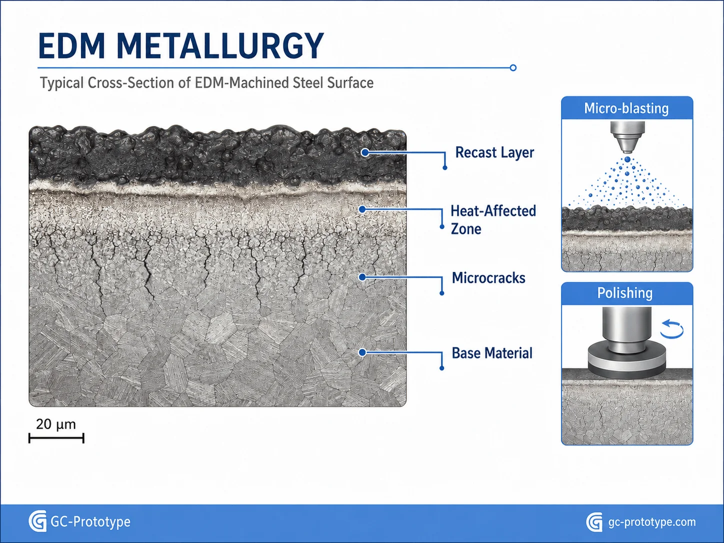
During EDM, a portion of the molten material is expelled from the discharge crater, while another portion rapidly resolidifies on the surface. This resolidified zone is known as the recast layer or white layer. Beneath it, the material may also contain a heat-affected zone with altered microstructure and residual stress.
The recast layer may contain microcracks, tensile residual stress, oxides, carbon contamination, or electrode material. Its significance depends on alloy, pulse energy, service load, corrosion exposure, and the location of the EDM surface.
A decorative mold cavity may tolerate a controlled spark-eroded layer. A highly loaded aerospace spline, surgical instrument, spring component, or pressure-critical feature may require the affected layer to be minimized or removed.
Common removal and control methods include:
Multiple low-energy EDM finishing passes
Micro-blasting with controlled media
Fine grinding or honing
Mechanical polishing or lapping
Chemical polishing
Electropolishing
Electrochemical machining or electrochemical grinding
Light abrasive-flow finishing
Laser or plasma-based finishing in specialized applications
Micro-blasting can remove weak surface material and create a uniform matte appearance, but excessive pressure or aggressive media can round edges or alter dimensions. Mechanical polishing is effective on accessible surfaces but depends heavily on operator skill and may distort precision geometry.
Chemical and electrochemical methods can treat complex shapes with less mechanical force. They require careful control of chemistry, masking, dimensional allowance, and waste handling. Electropolishing is particularly useful for selected stainless steel medical and fluid-handling components because it can reduce microscopic peaks and improve cleanability.
For high-reliability components, removal should be verified rather than assumed. A quality plan may require metallographic cross-sections, microhardness testing, surface roughness measurement, dye penetrant inspection, scanning electron microscopy, or fatigue validation.
Financial Trade-Offs: edm surface treatment vs manual polishing cost
The edm surface treatment vs manual polishing cost comparison should evaluate total ownership cost rather than only machine-hour rate. Mirror EDM and fine spark finishing may have a higher hourly machine cost, but they can reduce manual polishing time, rework, dimensional drift, and schedule uncertainty.
Manual polishing remains important for optical surfaces, mirror-finish cavities, repair work, and areas where the final visual requirement cannot be achieved directly by EDM. However, hand polishing introduces operator variation. Aggressive polishing can round corners, change shutoff geometry, reduce texture consistency, or push critical dimensions outside tolerance.
| Cost Factor | Fine or Mirror EDM | Manual Polishing |
| Equipment rate | Higher | Lower equipment cost |
| Labor dependence | Moderate | High |
| Repeatability | High with stable technology | Operator-dependent |
| Risk to sharp geometry | Low when process is controlled | Higher if over-polished |
| Deep-cavity access | Strong advantage | Difficult |
| Final optical gloss | May require further polishing | Strong for accessible surfaces |
| Lead-time predictability | Relatively stable | Depends on technician availability |
A practical strategy is to use EDM to approach the final surface as closely as possible, then apply limited polishing only where necessary. This hybrid approach reduces handwork while preserving the ability to achieve optical or premium cosmetic finishes.
Claims that mirror EDM eliminates a fixed percentage of polishing time should be treated cautiously because savings depend on cavity depth, steel grade, required finish, electrode quality, machine capability, and operator skill. For some tools, polishing labor may fall dramatically. For others, EDM mainly reduces the number of manual stages.
Procurement teams should request quotations that separate electrode manufacture, rough EDM, finishing passes, polishing, inspection, and rework assumptions. This exposes the true cost drivers and makes design changes easier to evaluate.

Advanced Process DFM & Supplier Selection
Engineering Best Practices for EDM Tooling and Cavity Design
Good EDM DFM begins with electrode access, discharge-gap compensation, flushing, tool rigidity, and inspection. A geometry that can be modeled in CAD is not automatically efficient to manufacture.
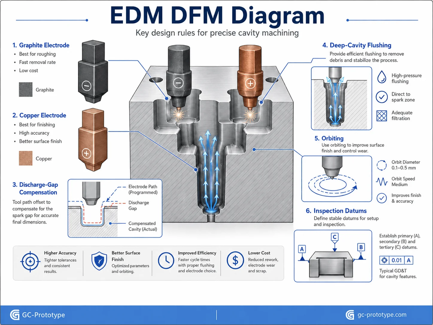
Graphite electrodes offer high material-removal efficiency, good machinability, and resistance to thermal damage. They are widely used for general mold cavities and roughing. Copper electrodes provide excellent detail and surface quality but may machine more slowly. Copper-tungsten is suitable for fine features, difficult alloys, and applications requiring high electrode stability.
| Electrode Material | Main Advantage | Typical Limitation | Best Application |
| Graphite | Fast machining and good roughing performance | Dust and fragile fine edges | General cavities and ribs |
| Copper | Fine detail and stable finishing | Higher machining time | Precision mold surfaces |
| Copper-tungsten | Strong wear resistance and detail retention | High material cost | Micro-features and demanding alloys |
The electrode must be designed smaller than the final cavity to account for the discharge gap. Different roughing and finishing parameters create different overcut values, so separate electrodes may be required.
Deep, narrow cavities are particularly difficult because debris must escape through a restricted gap. Poor flushing can cause unstable arcing, local burning, carbon deposition, excessive electrode wear, and inconsistent texture. Flushing holes, vent grooves, orbiting strategies, and segmented electrodes may improve process stability.
Practical DFM recommendations include:
Pre-machine bulk material by CNC before EDM
Avoid unnecessarily deep and narrow ribs
Use practical internal radii
Provide flushing access
Separate roughing and finishing electrodes
Protect fragile electrode details
Define cosmetic and functional surfaces
Add stock for post-EDM polishing where required
Plan inspection access
Avoid placing critical dimensions across unstable electrode split lines
Preventing Carbon Deposition and Unstable Discharge
Carbon deposition can occur when debris remains in the gap and discharges become unstable. The result may be pitting, black deposits, poor texture, and dimensional variation.
Prevention depends on dielectric cleanliness, adequate flushing pressure, correct pulse settings, electrode movement, sufficient gap, and stable temperature. Deep cavities may require programmed jump cycles or orbiting to renew dielectric fluid and remove debris.
The goal is not maximum flushing pressure at all times. Excessive pressure can deflect a small electrode, disturb the gap, or create non-uniform wear. The process should be optimized for the cavity geometry and electrode stiffness.
Inspection and Quality-Control Requirements
A complete EDM inspection plan may include:
Profilometer measurement of Ra or Rz
Visual comparison with approved VDI plaques
CMM inspection of cavity geometry
Optical measurement of micro-features
Wire-cut profile and taper inspection
Metallographic recast-layer measurement
Microcrack inspection
Electrode wear verification
Surface contamination checks
First-article and final inspection reports
The drawing should state where roughness is measured and whether the value applies before or after recast-layer removal, polishing, coating, or heat treatment.
Cost Analysis and Procurement Strategy
EDM cost is driven by electrode manufacture, machine time, roughing volume, finishing passes, flushing difficulty, electrode wear, inspection, and post-processing. Material hardness has less influence than in conventional cutting, but geometry and surface requirements strongly affect cycle time.
| Cost Driver | Why It Raises Cost | Cost-Reduction Strategy |
| Large removal volume | Long machine time and electrode wear | CNC pre-roughing |
| Deep narrow cavity | Poor flushing and slow cutting | Widen, shorten, or segment |
| Ultra-fine Ra | Multiple finishing passes | Limit to critical surfaces |
| Complex electrode | More programming and electrode machining | Simplify or standardize |
| Tight tolerance everywhere | Longer finishing and inspection | Prioritize functional features |
| Recast-layer removal | Additional processing and validation | Apply only where required |
| Manual polishing | Skilled labor and schedule risk | Use fine EDM before polishing |
Senior Engineers and Sourcing Managers should review cost at the feature level. A fine finish on one sealing surface may be justified, while applying the same finish to every hidden cavity can add days of machine time.
A complete RFQ should include the 3D model, 2D drawing, material and hardness, quantity, VDI grade, Ra or Rz requirement, recast-layer limit, critical tolerances, inspection method, post-processing, and delivery target.
Application Scenarios
Aerospace Spline and Actuator Component
An aerospace supplier needs a hardened alloy spline with tight profile control and high fatigue reliability. Wire EDM produces the geometry, while multiple skim passes reduce roughness. Recast-layer requirements are verified by metallographic inspection.
Medical Surgical Instrument
A medical R&D team requires narrow slots and precision gripping features in hardened stainless steel. EDM avoids excessive cutting force, while electropolishing removes surface irregularities and improves cleanability.
Consumer Electronics Injection Mold
A product designer specifies a fine matte texture for a smart-hardware enclosure. Sinker EDM produces an approved VDI texture directly in the cavity, reducing separate texturing operations.
Robotics Gear and Precision Joint
A robotics manufacturer needs small hardened gears and shaft profiles with controlled runout. Wire EDM supports accurate geometry without conventional tool pressure.
Automotive Connector Mold
A moldmaker uses copper electrodes to produce deep ribs and connector details in hardened tool steel. Controlled finishing passes reduce polishing work and preserve sharp geometry.
Frequently Asked Questions
What Is EDM Surface Treatment?
EDM surface treatment refers to the controlled spark-eroded surface created by sinker or wire EDM and the finishing processes used to refine roughness, texture, and surface integrity.
What Is the VDI 3400 Standard?
VDI 3400 is a widely used reference for spark-eroded mold textures. Lower grades represent finer surfaces, while higher grades represent coarser textures.
What Ra Can Wire EDM Achieve?
A rough cut may leave Ra values of several micrometers. Multiple skim passes can reduce roughness to approximately Ra 0.2–0.5 µm, while specialized fine-finish systems may achieve lower values under suitable conditions.
What Is the EDM Recast Layer?
The recast layer is resolidified material left after electrical discharges melt the workpiece surface. It may contain altered microstructure, residual stress, microcracks, or contamination.
How Is the Recast Layer Removed?
Common methods include low-energy finishing passes, micro-blasting, grinding, polishing, electropolishing, chemical polishing, and electrochemical processing.
Is Mirror EDM Cheaper Than Manual Polishing?
It can reduce polishing labor and dimensional risk, especially in deep cavities. The final economics depend on geometry, steel, required gloss, machine capability, and inspection.
Can EDM Texture Replace Chemical Etching?
For many matte spark textures, yes. Complex decorative grains and branded patterns may still require chemical or laser texturing.
Which Electrode Material Is Best?
Graphite is efficient for general roughing and cavities. Copper is strong for fine finishing, while copper-tungsten supports micro-features and demanding wear conditions.
How Can EDM Cost Be Reduced?
Pre-machine bulk material, simplify deep narrow features, use realistic surface specifications, and limit recast-layer removal and fine finishing to critical areas.
What Information Is Needed for an EDM Quotation?
Provide CAD files, material and hardness, quantity, tolerances, VDI or Ra requirements, recast-layer limits, inspection needs, post-processing, and delivery expectations.
EDM surface treatment is indispensable when hardened materials, deep cavities, precision profiles, or micro-features exceed the practical limits of conventional machining. Its value comes from combining geometric freedom with controlled texture, low mechanical force, and repeatable surface finishing.
The strongest results depend on realistic VDI and Ra specifications, appropriate electrode selection, stable flushing, controlled discharge energy, verified recast-layer removal, and a supplier capable of both precision machining and surface inspection.
Achieving flawless surface integrity and exact texture tolerances on hardened tool steels should not compromise your project timeline. Whether you are a Senior Mechanical Engineer designing high-fatigue aerospace components or a Sourcing Manager looking to reduce manual polishing overhead, GC Prototype delivers precision EDM solutions.
Our capabilities include sinker EDM, wire EDM, fine and mirror finishing, graphite and copper electrode manufacturing, VDI texture control, recast-layer management, dimensional inspection, and low-volume precision manufacturing.