Address:
Shenzhen Bao'an District Xinqiao Subdistrict Huangpu Community Huangpu East Ring Road No. 504 Shenzhen Yuan Industrial City Building C
Work Hours:
Monday to Friday: 9AM - 21PM
Weekend: 9AM - 21PM

Address:
Shenzhen Bao'an District Xinqiao Subdistrict Huangpu Community Huangpu East Ring Road No. 504 Shenzhen Yuan Industrial City Building C
Work Hours:
Monday to Friday: 9AM - 21PM
Weekend: 9AM - 21PM

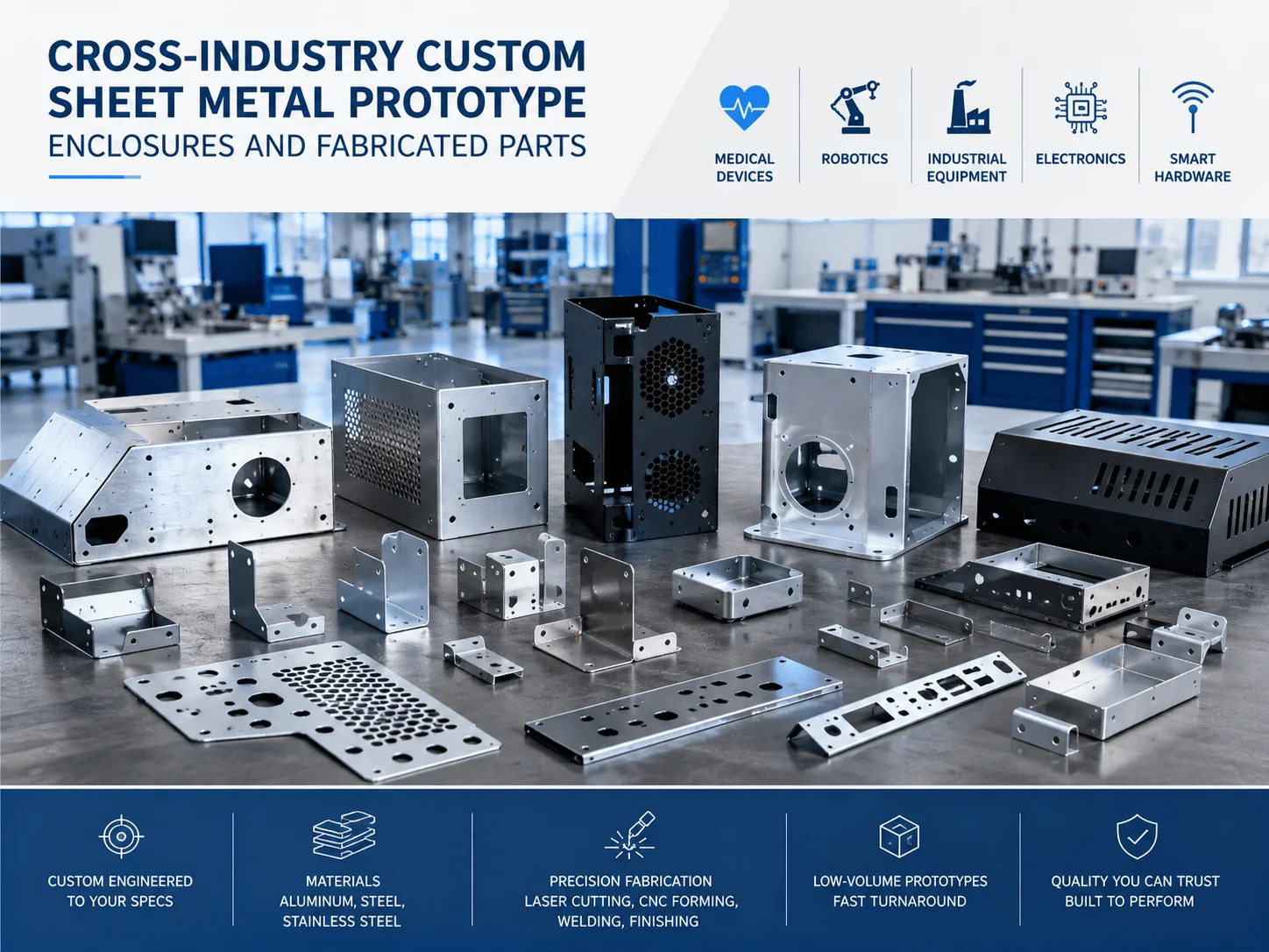
Sheet metal is essential for protecting electronics, medical instruments, robotic controllers, power systems, and industrial assemblies. It provides structural strength, heat dissipation, electromagnetic shielding, service access, and a durable external appearance without the tooling investment required by many molded processes. For Senior Mechanical Engineers, Product Designers, NPI Managers, and Procurement Professionals, successful sheet metal development depends on more than choosing a material and sending a CAD model to a supplier.
The design must account for bend behavior, hole placement, tooling access, fasteners, welding, finishing, tolerance stack-up, inspection, and expected production quantity. Decisions made during the first CAD review can determine whether a prototype is delivered quickly or becomes trapped in repeated revisions and unexpected fabrication costs.
This guide presents a practical framework for designing custom enclosures, completing DFM reviews, controlling prototype risk, and managing low-volume production costs across medical devices, consumer electronics, robotics, automation, aerospace, and industrial equipment.
How Sheet Metal Fabrication Works
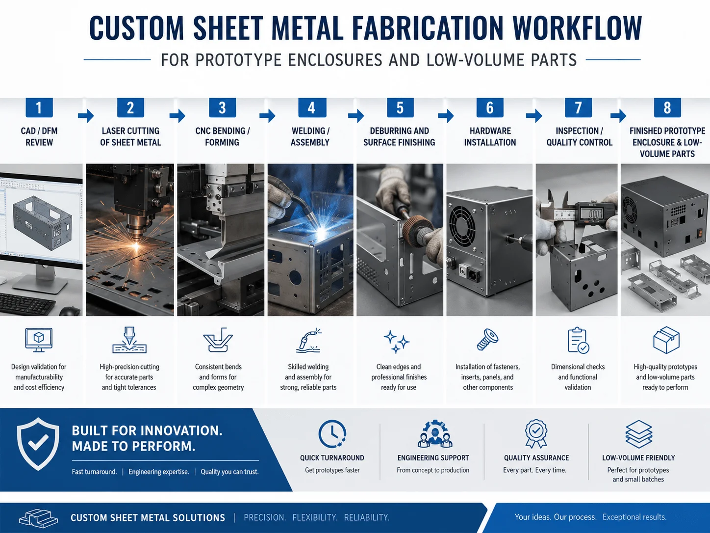
Sheet metal fabrication converts flat metal stock into three-dimensional components through cutting, forming, joining, and finishing. A typical enclosure may begin as a laser-cut flat pattern, then move through deburring, press-brake bending, hardware installation, welding, grinding, coating, printing, inspection, and final assembly.
The process is flexible because it does not require a dedicated production mold for each new design. Laser cutting and CNC bending can support one prototype, a 20-piece engineering batch, or a 200-piece pilot run with relatively limited tooling.
Common fabrication processes include:
Fiber laser cutting for profiles, holes, slots, and ventilation patterns
CNC punching for repeatable holes and standard formed features
Press-brake bending for flanges, channels, covers, and chassis
TIG, MIG, spot, and laser welding for permanent assemblies
PEM hardware, rivet nuts, studs, and inserts for mechanical assembly
Powder coating, anodizing, passivation, brushing, and polishing
Silk-screen printing and laser marking for branding and labels
| Process | Best Use | Main Advantage | Typical Limitation |
| Laser cutting | Flexible flat profiles | Fast setup and high design freedom | Heat-affected edges may need cleanup |
| CNC punching | Repeated holes and louvers | Efficient for standard features | Tool availability limits geometry |
| Press-brake bending | Enclosures and brackets | Accurate, repeatable forming | Tooling access must be considered |
| Welding | Frames and sealed assemblies | Strong permanent joints | Heat may cause distortion |
| Mechanical fastening | Serviceable products | Easy disassembly and repair | Adds hardware and assembly steps |
| Powder coating | Durable colored finish | Strong wear and corrosion resistance | Coating thickness affects fit |
Precision Enclosures Across Industries
Engineering Precision: Sourcing custom sheet metal prototype enclosures
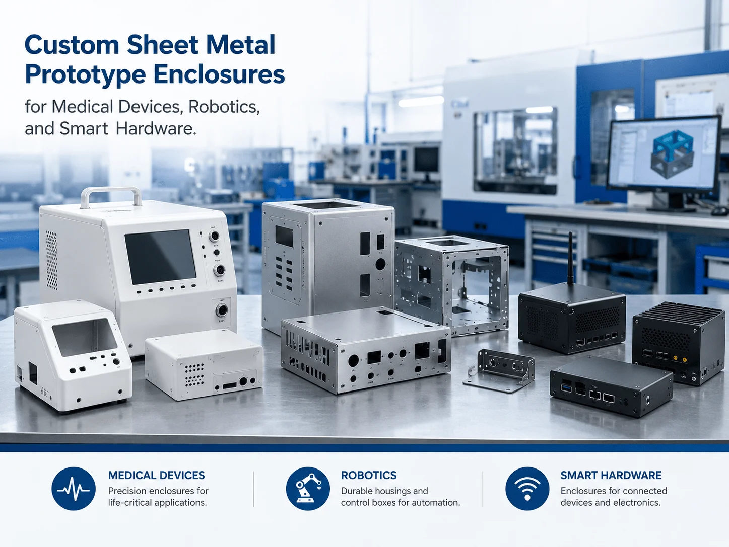
Sourcing custom sheet metal prototype enclosures requires balancing mechanical strength, internal component layout, thermal management, EMI shielding, serviceability, and visual design. A technically successful enclosure must protect the product while remaining practical to manufacture and assemble.
For medical diagnostic equipment, the housing may need smooth cleanable surfaces, corrosion-resistant stainless steel, controlled seams, and safe edge conditions. For robotics, the enclosure may need to resist vibration while providing access to motors, sensors, connectors, and cable routes. Consumer electronics often require a premium finish, narrow panel gaps, ventilation, and accurate alignment around displays and ports.
A prototype enclosure should validate:
PCB and electronic component clearance
Connector, display, and switch alignment
Cable routing and strain relief
Fan placement and airflow
Heat-sink or thermal-pad contact
Door, lid, and service-panel access
Fastener installation and tool clearance
Structural stiffness
Grounding and EMI continuity
Exterior appearance and finish
Material selection strongly affects performance. Aluminum is lightweight, corrosion resistant, and suitable for anodizing. Cold-rolled steel is strong and economical but usually requires painting or powder coating. Stainless steel offers excellent corrosion resistance and cleanability, although it requires greater forming force and generally costs more.
| Material | Key Advantages | Typical Enclosure Applications |
| Aluminum 5052 | Lightweight and highly formable | Electronics, robotics, portable equipment |
| Aluminum 6061 | Strong and machinable | Frames, machined panels, structural bases |
| Cold-rolled steel | Strong and cost-effective | Industrial cabinets and control boxes |
| Stainless steel 304 | Durable and corrosion resistant | Medical, laboratory, food equipment |
| Stainless steel 316L | Strong chemical resistance | Medical and harsh-environment equipment |
| Galvanized steel | Improved corrosion protection | Industrial and outdoor cabinets |
Electromagnetic shielding should be considered before a cosmetic finish is specified. Powder coating and anodizing can insulate mating surfaces, reducing electrical continuity between panels. Grounding points, gasket contact zones, and bonding surfaces may need masking or conductive finishing.
Thermal design also influences geometry. Ventilation slots, fan openings, perforated panels, louvers, heat-sink mounts, and internal airflow paths should be evaluated with the electronic layout. A visually attractive enclosure can still fail if it traps heat or blocks maintenance access.
Design for Manufacturability & Defect Prevention
Essential Rules: Practical sheet metal prototyping tips for engineers
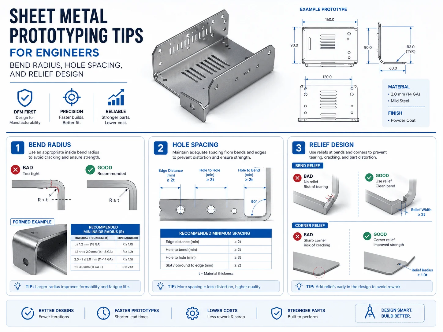
These practical sheet metal prototyping tips for engineers address the design issues most likely to increase quotation time, fabrication risk, and unit cost.
Keep the Material Thickness Consistent
An individual sheet metal part should normally use one consistent thickness. Local thickness changes usually require separate components, machining, welding, or another process.
Consistent thickness simplifies purchasing, flat-pattern development, bend compensation, and inspection. It also makes future production easier to scale.
Use a Realistic Minimum Bend Radius
An excessively small bend radius can stretch the outside surface and compress the inside surface beyond the material’s capability, causing cracks or visible deformation. The correct radius depends on material, temper, grain direction, thickness, and tooling.
For many common materials, a bend radius near the material thickness is a reasonable early design assumption, but the supplier should confirm the final value.
Keep Holes Away from Bend Lines
Holes and slots placed too close to a bend may stretch, become oval, or move during forming. A practical starting rule is to keep the nearest edge of a hole approximately 2 to 2.5 times the sheet thickness away from the bend line, with additional allowance for the bend radius and feature size.
Critical holes can also be added after bending, but secondary drilling or machining increases cost. Designing sufficient clearance into the flat pattern is usually more economical.
Add Bend Relief at Flange Intersections
Bend relief prevents tearing and uncontrolled deformation where multiple bends meet. Relief geometry should be simple, wide enough for the process, and positioned so it does not weaken a functional corner.
Design for Press-Brake Access
Deep boxes, narrow channels, return flanges, and closely spaced bends can interfere with the punch, die, or previously formed walls. A shape that appears straightforward in CAD may require special tooling or an impossible bend sequence.
The supplier should review bend order and tool clearance before production. In some cases, dividing a deep enclosure into two fastened or welded parts reduces both risk and cost.
Select Fasteners Early
PEM nuts, studs, rivet nuts, welded nuts, screws, and tabs affect hole size, installation direction, clearance, and bend sequence. Hardware specifications should appear in the drawing or bill of materials.
Define Cosmetic Surfaces
Mark visible Class-A surfaces and allow a more practical finish on hidden areas. Requiring perfect grinding, brushing, or coating on every surface increases labor and handling risk without improving the product.
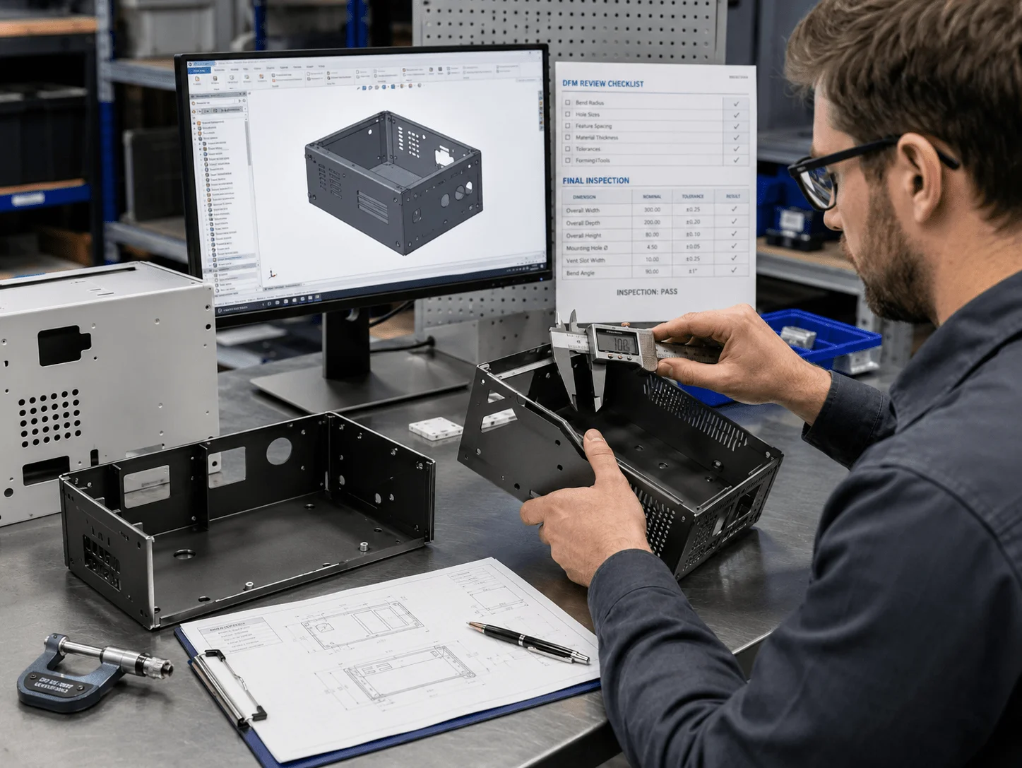
Quality Assurance: Establishing a sheet metal dfm review checklist
A formal sheet metal dfm review checklist helps NPI Engineers and Manufacturing Managers identify fabrication problems before material is cut. It also creates a repeatable communication process between design, purchasing, quality, and the supplier.
Geometry and Flat Pattern
Is the material grade and thickness clearly specified?
Are all bend radii achievable with available tooling?
Are holes and slots positioned safely away from bend lines?
Are bend reliefs included where flanges intersect?
Can every bend be completed without tool interference?
Has bend allowance or bend deduction been handled consistently?
Are grain-direction requirements necessary?
Is the flat pattern controlled by the designer or the fabricator?
The fabricator normally has the best knowledge of its bend tables and tooling. Many engineering teams therefore provide the formed 3D model and allow the supplier to generate the manufacturing flat pattern.
Hardware and Assembly
Are PEM hardware type, thread, and installation side identified?
Is there enough space for insertion tooling?
Will installed hardware interfere with later bends?
Can assembly tools reach every screw and nut?
Are cable, connector, and PCB clearances verified?
Is the required assembly sequence practical?
Welding and Distortion
Can the welder access the joint?
Is continuous welding necessary, or can stitch welding be used?
Can tabs, slots, rivets, or screws replace non-critical welds?
Does the assembly require a fixture?
Are long weld seams likely to distort large panels?
Are cosmetic welds clearly identified?
Welding introduces heat and localized shrinkage. Large flat panels and asymmetric structures are particularly sensitive. Reducing weld length, balancing the weld sequence, and adding self-locating tabs can improve consistency.
Finishing
Is the finish compatible with the material?
Are color, gloss, and texture defined?
Are masked grounding or sealing areas shown?
Has coating thickness been included in fit calculations?
Are threaded holes protected?
Are visible surfaces identified?
Tolerances and Inspection
Are datums clear and functional?
Are tight tolerances limited to critical interfaces?
Are formed dimensions measured in the correct condition?
Is a first-article report required?
Are material certificates or coating certificates required?
Are cosmetic acceptance criteria documented?
A good DFM review does not simply reject difficult features. It explains the manufacturing risk and proposes an alternative that preserves product function.
Procurement Strategy & Scaling
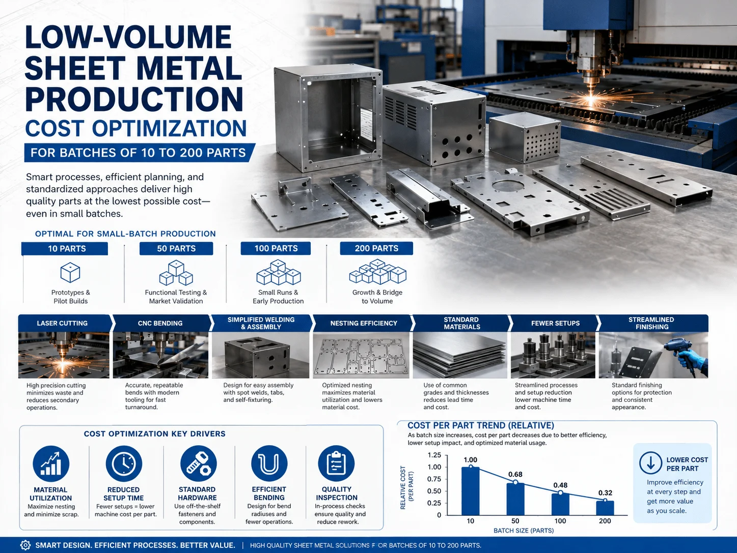
Financial Control: Managing low volume sheet metal production cost
Managing low volume sheet metal production cost requires separating one-time setup expenses from recurring part costs. For batches of 10 to 200 pieces, sheet metal is attractive because laser cutting and CNC bending do not require a dedicated hard tool. However, manual welding, grinding, finishing, and inspection can still dominate the quotation.
The main cost drivers include:
Material type, thickness, and utilization
Laser cutting time
Number of bends
Bend complexity and setup changes
Hardware quantity
Welding length and fixture requirements
Grinding and cosmetic finishing
Powder-coating minimum charges
Inspection and documentation
Assembly and packaging
| Quantity | Typical Manufacturing Approach | Cost Behavior |
| 1–5 parts | Prototype setup and manual processing | Highest unit cost |
| 6–20 parts | Reusable programs and simple fixtures | Setup cost begins to spread |
| 21–100 parts | Batch cutting, forming, and inspection | Stronger unit economics |
| 101–200 parts | Optimized nesting and repeatable fixtures | Lower unit cost |
| 200+ parts | Review dedicated punching or forming tools | Process-dependent |
Use Standard Material Thicknesses
Standard gauges are easier to source, less expensive, and more predictable to bend. Unusual thicknesses can increase raw-material price and lead time.
Improve Sheet Nesting
Parts should be arranged efficiently on the sheet to reduce scrap. Ordering related parts in one batch can improve material utilization.
Reduce Unnecessary Welding
Welding is labor-intensive and may require grinding, straightening, and inspection. Tabs, slots, PEM fasteners, screws, rivets, or folded seams can reduce weld length where permanent sealing is not required.
Standardize Hardware
Using a limited range of common PEM nuts, studs, and screws simplifies purchasing, installation, and quality control. Custom hardware should be reserved for real functional needs.
Limit Cosmetic Finishing
Powder coating, brushing, polishing, and painting add labor. Identify visible surfaces and avoid premium cosmetic requirements inside hidden compartments.
Consolidate Process Steps
A one-stop supplier that provides cutting, bending, hardware, welding, coating, printing, inspection, and assembly can reduce transport, communication delays, and revision errors.
Cost Comparison: Fabrication Options for a Low-Volume Enclosure
| Option | Upfront Investment | Unit Cost at Low Volume | Design Flexibility | Best Use |
| Sheet metal fabrication | Low | Moderate | High | Enclosures, chassis, brackets |
| CNC machining from billet | Low | High | High | Thick precision housings |
| Urethane casting | Moderate | Moderate | Medium | Plastic-like cosmetic parts |
| Injection molding | High | Low after tooling | Low after tool approval | Stable high-volume plastic parts |
| Die casting | High | Low after tooling | Low after tool approval | Stable metal production parts |
For 10 to 200 metal enclosures, sheet fabrication often offers the strongest balance of low upfront investment, real production materials, design flexibility, and acceptable unit economics.
Application Scenarios
Medical Diagnostic Enclosure
A medical technology company requires 25 stainless steel housings for a diagnostic instrument. The design needs cleanable surfaces, removable service panels, cable access, and a stable mounting structure.
Stainless steel provides corrosion resistance, while controlled welds and brushed finishing create a professional appearance. A first-article build verifies assembly access and cleaning before the full batch is released.
Robotics Controller Housing
A robotics company needs an aluminum controller enclosure with ventilation, internal rails, EMI grounding, and several connector cutouts.
Laser cutting supports rapid design changes, while CNC bending produces a lightweight structure. Masked grounding points preserve electrical continuity after powder coating.
Consumer Electronics Chassis
A hardware startup requires 80 chassis for a pilot launch. The parts need accurate port alignment, anodized aluminum panels, and silk-screened labels.
Sheet metal avoids injection-molding tooling and allows the design to be revised after field feedback.
Industrial Automation Cabinet
An automation integrator requires 50 control boxes in several configurations. Standardizing material, hardware, and panel geometry lowers cost, while configurable cutouts support different customer requirements.
Aerospace Test Equipment
An aerospace R&D team needs lightweight brackets, equipment trays, and protective panels for a test system. The supplier uses controlled bend processes and documented inspection for critical interfaces.
Automotive Battery-Electronics Cover
An automotive development program requires aluminum covers with stiffening beads, gasket surfaces, and fastener locations. Prototype fabrication allows the team to test fit, vibration, and service access before production tooling is considered.
Selecting a Sheet Metal Manufacturing Partner
A supplier should be evaluated on engineering capability, process control, communication, and scalability—not only on quoted price.
A capable partner should provide:
DFM feedback
Laser cutting and CNC punching
Press-brake bending
Hardware installation
Welding and grinding
Powder coating and anodizing
Silk-screen printing and laser marking
Dimensional inspection
Prototype assembly
Low-volume production
Revision and traceability control
The RFQ package should include:
STEP or native 3D CAD files
Dimensioned 2D drawings
Material grade and thickness
Required quantity
Finish and color
Hardware specifications
Welding symbols
Critical dimensions
Cosmetic surface requirements
Inspection documentation
Delivery target
Ask the supplier how it handles first-article approval, engineering changes, color standards, coating defects, welding distortion, and packaging. A fast quotation is valuable, but a technically complete quotation is more important.
Frequently Asked Questions
What Is the Best Material for a Sheet Metal Enclosure?
Aluminum is ideal when low weight and corrosion resistance matter. Cold-rolled steel provides strength at a competitive cost. Stainless steel is suitable for medical, laboratory, food, and harsh-environment applications.
How Close Can a Hole Be to a Bend?
A practical starting point is to keep the nearest hole edge approximately 2 to 2.5 times the material thickness from the bend line, with additional consideration for bend radius and hole size. The supplier should confirm the final requirement.
What Is the Minimum Bend Radius?
The appropriate radius depends on material, thickness, temper, grain direction, and tooling. A radius near one material thickness is a useful early assumption for many common metals, but it is not universal.
How Can Welding Distortion Be Reduced?
Reduce weld length, use balanced weld sequences, add fixtures, replace non-critical welds with mechanical fasteners, and avoid concentrating heat on large unsupported panels.
Should Designers Provide the Flat Pattern?
A formed 3D model and dimensioned drawing are usually essential. The fabricator may prefer to create the manufacturing flat pattern using its own bend allowances, machines, and tooling data.
How Does Powder Coating Affect Dimensions?
Powder coating adds thickness to exposed surfaces and can reduce clearance around slots, hinges, threads, grounding points, and mating panels. Critical areas should be masked or designed with suitable allowance.
Is Sheet Metal Economical for 10 to 200 Parts?
Yes. This quantity range often fits laser cutting and CNC bending well because no dedicated production mold is required. Cost depends strongly on welding, finishing, and assembly complexity.
What Files Are Needed for a Quotation?
Provide a solid 3D CAD model, a dimensioned 2D drawing, material, thickness, quantity, finish, hardware, welding requirements, critical tolerances, and delivery expectations.
How Can Enclosure Costs Be Reduced?
Use standard material thicknesses, simplify bends, improve sheet nesting, standardize hardware, reduce welding, restrict cosmetic finishing to visible areas, and consolidate processes with one supplier.
Can a Prototype Supplier Also Support Low-Volume Production?
Yes, provided the supplier has repeatable tooling, inspection capability, finishing control, revision management, and sufficient production capacity.
Sheet metal fabrication provides a flexible and production-relevant path from concept validation to low-volume manufacturing. It protects sensitive electronics, supports medical and robotics equipment, manages heat, enables electromagnetic shielding, and delivers durable professional enclosures without large tooling investments.
Strong results begin with consistent material thickness, practical bend radii, adequate hole clearance, accessible hardware, controlled welding, and realistic tolerance requirements. A structured DFM review then identifies risks before cutting begins.
For Procurement Managers and Strategic Buyers, cost control comes from standard materials, efficient nesting, reduced manual welding, common hardware, focused cosmetic requirements, and a supplier capable of managing the complete workflow.
Accelerate Your Sheet Metal Project with GC Prototype
Bringing a custom metal housing from CAD to reality requires seamless alignment between geometric precision and cost-effective fabrication. Whether you are a Senior Mechanical Engineer optimizing a robotics enclosure or a Sourcing Manager looking to shorten NPI timelines, GC Prototype is your trusted manufacturing partner.
Our capabilities include laser cutting, CNC bending, hardware installation, precision welding, powder coating, anodizing, silk-screen printing, assembly, dimensional inspection, rapid prototyping, and low-volume production.