Address:
Shenzhen Bao'an District Xinqiao Subdistrict Huangpu Community Huangpu East Ring Road No. 504 Shenzhen Yuan Industrial City Building C
Work Hours:
Monday to Friday: 9AM - 21PM
Weekend: 9AM - 21PM

Address:
Shenzhen Bao'an District Xinqiao Subdistrict Huangpu Community Huangpu East Ring Road No. 504 Shenzhen Yuan Industrial City Building C
Work Hours:
Monday to Friday: 9AM - 21PM
Weekend: 9AM - 21PM

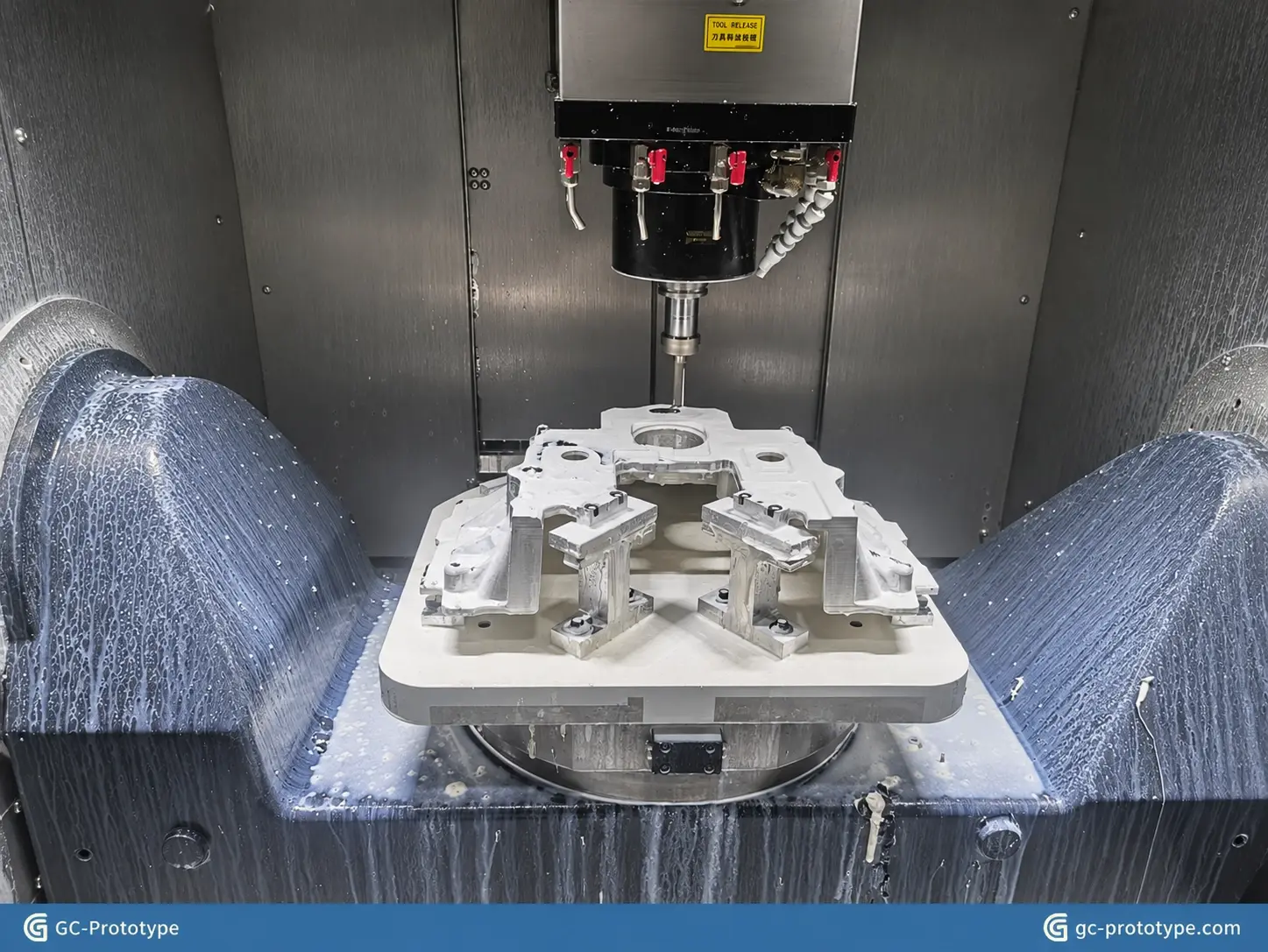
Precision CNC manufacturing is not simply about achieving the smallest possible machining tolerance. For OEM engineers and procurement teams, the real challenge is producing cnc precision parts that meet critical dimensional requirements, fit correctly within assemblies, and remain consistent across production batches.
From bearing housings and sensor mounts to precision mechanical connectors, successful manufacturing depends on datum selection, process stability, suitable inspection methods, and clear engineering documentation.
A reliable manufacturing partner should understand not only how to machine a component but also how to verify that it performs as intended.
At GC-Prototype, we support custom CNC machining projects from CAD review and prototype samples to functional validation, low-volume pilot production, and mass production support.
This guide explains how functional tolerances, manufacturing controls, dimensional inspection, and engineering communication contribute to reliable precision CNC components.
Precision CNC manufacturing involves producing components according to defined dimensional and geometric requirements using controlled machining and inspection processes.
However, accuracy, precision, and repeatability are not interchangeable.
Accuracy describes how closely a measured result agrees with its specified or reference value.
Precision describes how closely repeated measurements or manufacturing results agree with one another.
Repeatability refers to the consistency of results under defined conditions.
For example, a CNC machine may repeatedly produce a shaft diameter with very little variation, but the parts can still be inaccurate if the process is consistently offset from the drawing requirement.
A reliable manufacturing process must address both accuracy and repeatability.
Not every dimension requires the same level of control.
A bearing bore may need a tight tolerance to achieve the required fit, while an external nonfunctional surface may allow greater variation.
Engineering drawings should distinguish critical functional dimensions from general manufacturing dimensions.
Machine capability is only one factor influencing finished-part accuracy.
Other factors include:
Workholding stability.
Cutting tool condition.
Material properties.
Cutting forces.
Temperature variation.
Machining sequence.
Measurement methods.
Even advanced CNC equipment requires appropriate process planning and inspection to manufacture parts that meet demanding specifications.
Different mechanical components require different dimensional controls.
The most effective machining strategy begins by understanding how each part functions within its final assembly.
Aluminum housings are commonly used in robotics, electronics, industrial automation, and automotive equipment.
A housing may contain bearing bores, mounting holes, internal pockets, and machined reference surfaces.
For an actuator housing, the relationship between the bearing bore and motor mounting features may be more important than the overall external dimensions.
Bearing seats require suitable diameter, geometry, and surface conditions.
An incorrectly machined bearing interface may cause excessive clearance, assembly difficulty, misalignment, or premature component wear.
The appropriate fit should be specified according to the bearing arrangement and operating requirements.
Precision shafts may require controlled diameters, runout, straightness, and surface roughness.
Mechanical connectors can require accurate threads, mating surfaces, and positioning features.
The applicable tolerances depend on component function, material, and assembly conditions.
Sensor mounts and robotic components often require accurate relationships between mounting holes, reference surfaces, and mechanical interfaces.
Even relatively small positional errors can affect assembly or sensor alignment.
| CNC Precision Part | Critical Feature | Potential Functional Risk |
| Robotic Joint Housing | Bearing bore and position | Misalignment |
| Sensor Housing | Mounting datum and hole position | Positioning error |
| Precision Shaft | Diameter and runout | Poor bearing fit |
| Motor Mounting Plate | Flatness and hole position | Assembly misalignment |
| Fluid Component | Bore and sealing surface | Leakage or fit problems |
| Mechanical Connector | Thread and mating dimensions | Assembly failure |
These examples show why precision requirements should be defined according to component function rather than applying extremely tight tolerances to every surface.
Engineering drawings provide the technical foundation for precision manufacturing.
A 3D CAD model defines component geometry, while a properly prepared 2D drawing communicates the dimensional and inspection requirements.
Critical-to-function features directly influence assembly, performance, or reliability.
Examples include:
Bearing interfaces.
Shaft diameters.
Mounting-hole locations.
Sealing surfaces.
Alignment features.
Precision mating surfaces.
These features should receive appropriate tolerance and inspection requirements.
A datum establishes a reference used to define or measure component geometry.
For example, a robotic actuator housing may use a mounting face as its primary datum and a locating feature as another reference.
Other holes and bores can then be controlled relative to those datums.
Clear datum definitions help manufacturers plan machining setups and establish consistent inspection procedures.
Geometric Dimensioning and Tolerancing (GD&T) communicates requirements that ordinary linear dimensions may not fully describe.
Common controls include:
Position: Controls the location of a feature relative to specified datums.
Flatness: Controls the form of a surface.
Perpendicularity: Controls orientation relative to a datum.
Profile: Controls the geometry of a specified surface or feature.
Appropriate GD&T helps establish clear manufacturing and acceptance requirements.
Unnecessarily strict tolerances may increase machining time, fixture complexity, inspection requirements, and cost.
Instead of specifying maximum precision everywhere, engineers should evaluate which features actually affect product performance.
The best precision manufacturing strategy starts with functional requirements, not arbitrary tolerance numbers.
Producing a precise component requires controlling the entire machining process.
Even when the CAD model and CNC program remain unchanged, manufacturing conditions can affect the finished dimensions.
Workholding determines how securely a component is positioned during machining.
Insufficient support can allow vibration or movement, while excessive clamping force can distort thin-wall components.
Suitable fixtures should provide stable support without damaging critical features.
For complex parts, fixture design may also affect the ability to maintain relationships between multiple machined surfaces.
Cutting tools experience wear during machining.
As tool condition changes, dimensional accuracy and surface quality may also change.
Tool deflection can be particularly important when machining deep pockets, narrow features, or slender components.
Suitable tooling, cutting parameters, and process monitoring help reduce these effects.
Temperature can influence both machining and dimensional measurement.
Heat generated during cutting may affect tool condition and workpiece dimensions.
Materials also behave differently.
Aluminum, stainless steel, titanium, and engineering plastics have different thermal and mechanical properties.
Manufacturing strategies should account for the specific material and component geometry.
Some components require machining from multiple orientations.
Each additional setup introduces potential positioning variation.
For parts with critical relationships between several surfaces, the machining sequence should be planned carefully.
Where practical, reducing unnecessary setups may help control cumulative positioning errors.
Secondary operations can also affect finished dimensions.
For example, anodizing, plating, polishing, and heat treatment may influence dimensions or surface conditions.
Manufacturers should consider these effects when establishing machining allowances and inspection requirements.
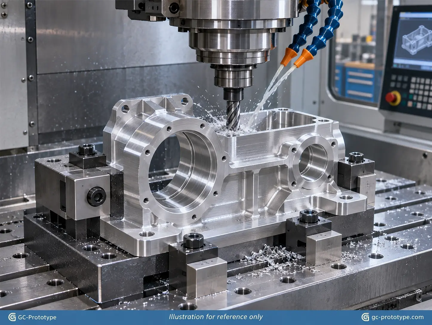
Dimensional inspection provides evidence that manufactured components conform to engineering requirements.
For every precision cnc machining part, the inspection approach should be based on its critical features, tolerances, and functional requirements.
Different features require different measurement methods.
A micrometer may be suitable for an accessible external diameter, while a bore gauge may be appropriate for an internal diameter.
Complex positional relationships may require a Coordinate Measuring Machine.
The selected measurement method should have suitable capability and uncertainty for the specified tolerance.
Coordinate Measuring Machines (CMM) are widely used to evaluate complex dimensions and geometric relationships.
Depending on equipment, probing configuration, and inspection strategy, CMM measurements may be used to evaluate:
Hole positions.
Bore dimensions.
Perpendicularity.
Parallelism.
Surface profiles.
Relationships between datums and features.
GC-Prototype uses Hexagon CMM equipment to support precision dimensional inspection.
However, measurement capability must be evaluated according to the actual feature geometry and tolerance.
Precision manufacturing may also require conventional measuring instruments and specialized gauges.
Examples include:
Micrometers for external dimensions.
Bore gauges for internal diameters.
Pin gauges for suitable holes.
Thread gauges for threaded features.
Runout measurement setups for rotating components.
Profilometers for specified surface roughness.
No single inspection instrument is appropriate for every feature.
Inspection results can be influenced by environmental temperature, instrument condition, measurement force, and workpiece stability.
For tight tolerances, measurement uncertainty becomes especially important.
Manufacturers should use appropriate measuring equipment and controlled inspection procedures to support reliable results.
For projects requiring detailed quality documentation, dimensional inspection reports can record measured results against drawing requirements.
These records help customers understand whether critical features meet the agreed specifications.
| Critical Feature | Suitable Inspection Method | What It Verifies |
| Bearing Bore Diameter | Bore gauge / suitable CMM method | Bore size |
| Hole Position | CMM | Position relative to datums |
| Mounting Face Flatness | CMM / suitable flatness measurement | Flatness |
| Shaft Runout | Appropriate runout measurement setup | Variation relative to datum axis |
| Thread | Thread gauges | Thread conformity |
| Surface Roughness | Profilometer | Specified surface roughness |
The appropriate method depends on the required tolerance, component accessibility, and measurement uncertainty.
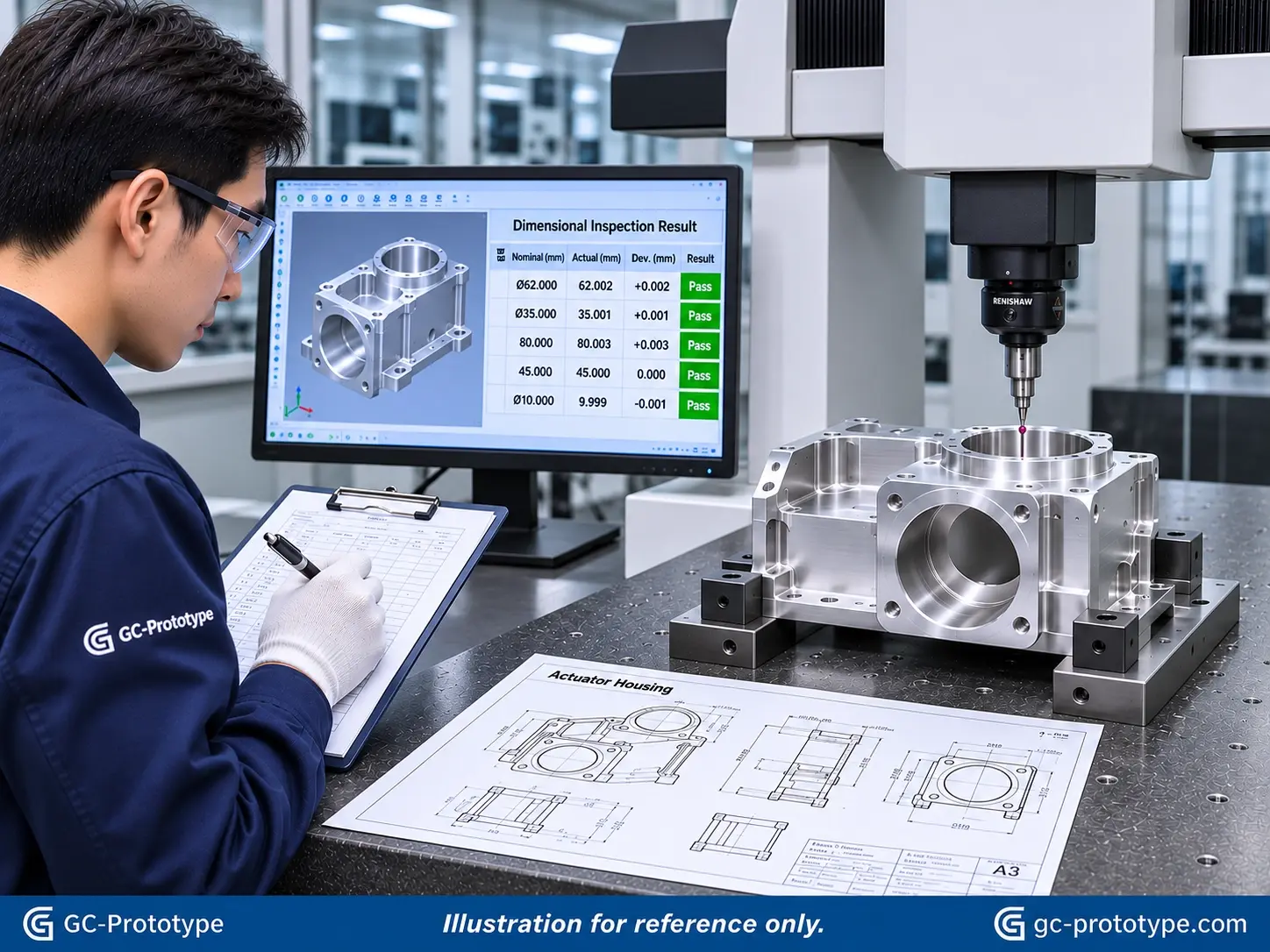
A successful prototype does not automatically guarantee that future production batches will have identical results.
Repeatability requires suitable manufacturing controls and clearly defined inspection requirements.
Initial production samples can be inspected to verify that the selected manufacturing setup produces acceptable components.
When required, First Article Inspection can provide more formal documentation of the initial manufacturing results.
During repeated manufacturing, tool wear, fixture condition, material variation, and machine setup can affect dimensional consistency.
Appropriate process monitoring and inspection help identify variation before it creates larger production problems.
Engineering changes should be clearly documented.
Production and inspection should follow the approved drawing revision for the applicable order.
This is especially important when a component undergoes several prototype iterations.
Batch acceptance criteria should be agreed upon before manufacturing.
Depending on the application, these may include dimensional sampling, visual inspection, material verification, or additional customer-specific requirements.
The goal is to maintain consistent component quality while avoiding unnecessary inspection costs.
Different materials and geometries create different challenges for precision manufacturing.
Aluminum is commonly used for lightweight housings, brackets, and structural components.
Stainless steel is frequently selected for mechanical components requiring corrosion resistance and durability.
Each material requires appropriate cutting conditions and manufacturing controls.
Engineering plastics such as POM, PEEK, Nylon, and PC may be used for precision mechanical components.
However, temperature changes, moisture absorption, and material flexibility can affect certain plastic dimensions.
Inspection requirements should account for relevant material behavior.
Thin walls, deep pockets, and complex internal features may increase workpiece deflection or limit tool access.
DFM review helps identify potential manufacturing difficulties before production begins.
For certain geometries, modifications to nonfunctional features can improve manufacturability without affecting component performance.
The total cost of precision CNC manufacturing depends on more than material and machining time.
Tolerances, inspection, workholding, surface requirements, and production quantity all influence pricing.
Tighter tolerances may require additional machining passes, controlled finishing operations, or specialized tooling.
The cost impact depends on component geometry and material.
Detailed inspection reports require measurement planning, equipment time, and documentation.
For components with numerous critical features, inspection can represent a meaningful portion of manufacturing costs.
Complex components may require custom fixtures or multiple machining setups.
Surface treatments and secondary operations can also influence dimensional requirements.
Cost optimization should focus on preserving critical functional requirements while simplifying unnecessary complexity.
For example, applying a tight tolerance only to bearing interfaces may be more economical than applying it to every external surface.
| Precision Requirement | Potential Cost Impact | Recommended Approach |
| Tight Bore Tolerance | Additional finishing and inspection | Apply to functional fits |
| Complex GD&T | More setup and measurement | Define clear datums |
| Thin-Wall Geometry | Deflection and rework risk | Review fixturing |
| Full Inspection Report | Additional inspection labor | Define required coverage |
| Fine Surface Finish | Additional operations | Specify critical surfaces |
| Multi-Face Features | More setups or complex machining | Review machining strategy |
The most effective cost-saving decisions are usually made during the engineering review stage.
GC-Prototype supports a manufacturing workflow connecting engineering review, prototype development, functional validation, and production planning.
Customers submit 3D CAD files and approved engineering drawings.
The engineering team reviews geometry, material specifications, critical dimensions, and manufacturing feasibility.
Initial samples are manufactured using suitable CNC machining processes.
These components can be evaluated for dimensions, assembly fit, and manufacturing feasibility.
Critical features are inspected according to the agreed requirements.
Where appropriate and agreed upon, dimensional reports can support engineering review and customer approval.
Customers evaluate the samples under relevant assembly and operating conditions.
After approval, suitable low-volume pilot production can help assess repeatability and prepare for subsequent orders.
GC-Prototype also supports manufacturing planning as projects progress toward larger production requirements.
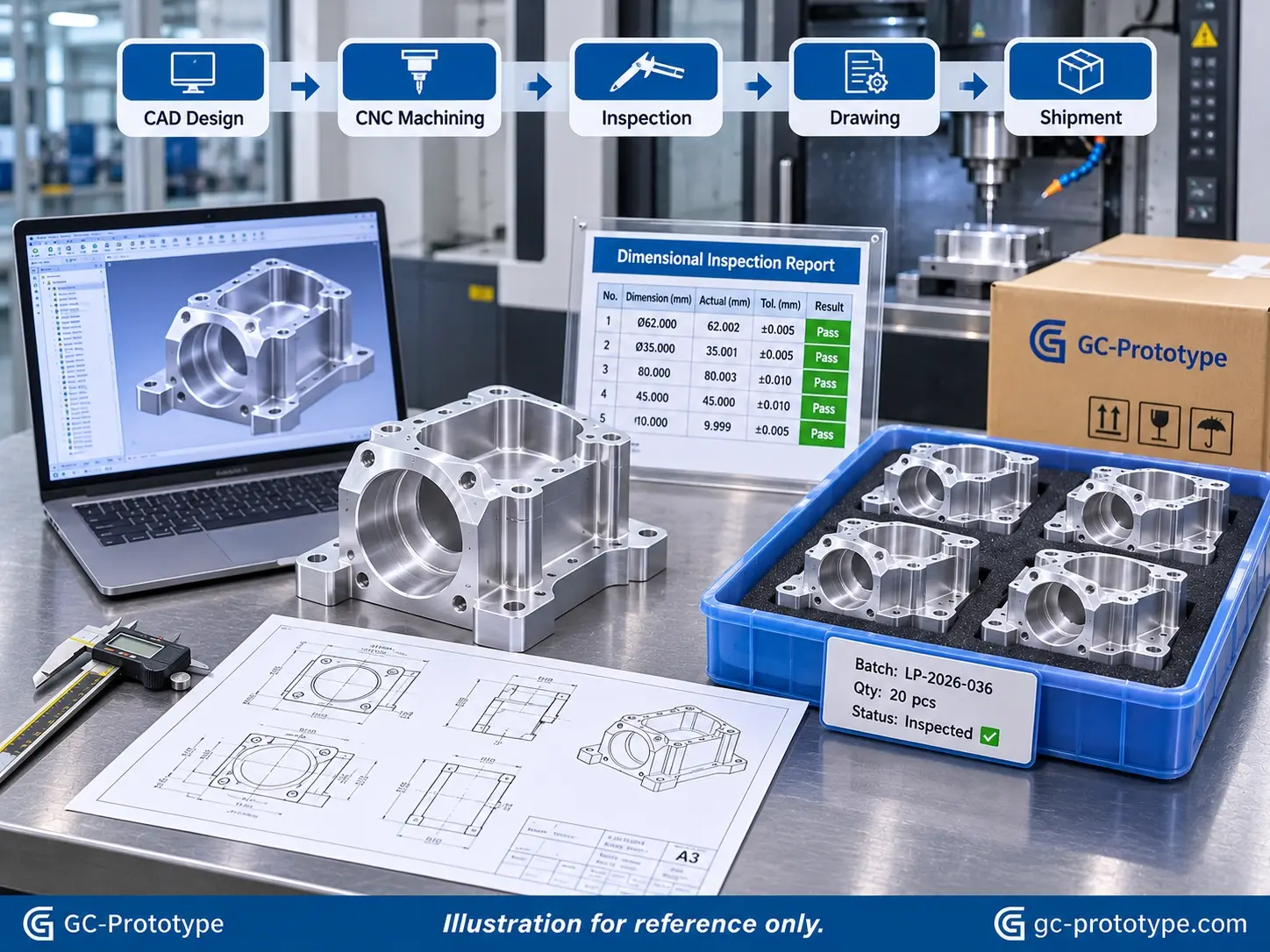
A complete Request for Quotation helps manufacturers understand the required accuracy and prepare an appropriate manufacturing proposal.
For cnc precision parts, technical documentation should clearly identify critical dimensions and acceptance requirements.
Provide a 3D STEP or STP model and a corresponding 2D engineering drawing.
The drawing should identify the approved revision and applicable technical specifications.
Specify the dimensions and geometric relationships that directly affect functionality.
This may include bore diameters, hole positions, flatness, runout, and other critical requirements.
Identify the required material grade, condition, surface finish, and any necessary secondary treatments.
Communicate whether dimensional reports, material certificates, First Article Inspection, or other documentation are required.
| RFQ Information | Recommended Details |
| 3D CAD | STEP / STP |
| 2D Drawing | PDF with revision |
| Material | Exact grade and condition |
| Critical Dimensions | Diameter, position, flatness, etc. |
| GD&T | Applicable datums and tolerances |
| Surface Finish | Ra or other relevant specifications |
| Quantity | Prototype and production quantities |
| Inspection | Required features and report format |
| Delivery | Destination and required schedule |
Providing accurate information reduces quotation uncertainty and helps align manufacturing expectations before production.
Precision CNC manufacturing involves producing components according to defined dimensional and geometric requirements using controlled machining processes and suitable inspection methods. It is commonly used for parts requiring accurate assembly interfaces and consistent performance.
Achievable tolerances depend on component geometry, material, machine capability, workholding, cutting tools, machining conditions, and measurement methods. Tolerance feasibility should be reviewed for each critical feature.
Manufacturers use suitable measurement instruments, including micrometers, bore gauges, CMM systems, thread gauges, and surface measurement equipment. Inspection methods are selected according to drawing requirements and feature geometry.
Dimensional accuracy describes how closely a manufactured feature matches its specified requirement. Repeatability describes how consistently the process produces similar results under defined conditions. A reliable process requires appropriate control of both.
No. Tight tolerances should be applied where necessary for assembly, function, or product reliability. Noncritical dimensions can often use more practical manufacturing tolerances, helping control cost without compromising performance.
Depending on project requirements, buyers may request dimensional inspection reports, material certificates, First Article Inspection records, and other agreed quality documents. Documentation requirements should be confirmed before manufacturing.
Looking for a reliable partner for precision cnc manufacturing and custom mechanical components?
GC-Prototype provides CNC milling, CNC turning, multi-axis machining, and dimensional inspection support for international B2B customers.
Whether your project involves precision aluminum housings, stainless steel connectors, robotic components, mechanical brackets, or complex custom parts, our team can review your engineering drawings and discuss suitable manufacturing solutions.
Send us your 3D CAD/STEP files and 2D engineering drawings, including material requirements, critical tolerances, and expected quantities.
Our engineering team can review manufacturing feasibility, dimensional requirements, and suitable machining approaches.
From CAD review and prototype samples to functional validation, low-volume pilot production, and mass production support, GC-Prototype helps engineering and procurement teams move their projects forward.