Address:
Shenzhen Bao'an District Xinqiao Subdistrict Huangpu Community Huangpu East Ring Road No. 504 Shenzhen Yuan Industrial City Building C
Work Hours:
Monday to Friday: 9AM - 21PM
Weekend: 9AM - 21PM

Address:
Shenzhen Bao'an District Xinqiao Subdistrict Huangpu Community Huangpu East Ring Road No. 504 Shenzhen Yuan Industrial City Building C
Work Hours:
Monday to Friday: 9AM - 21PM
Weekend: 9AM - 21PM

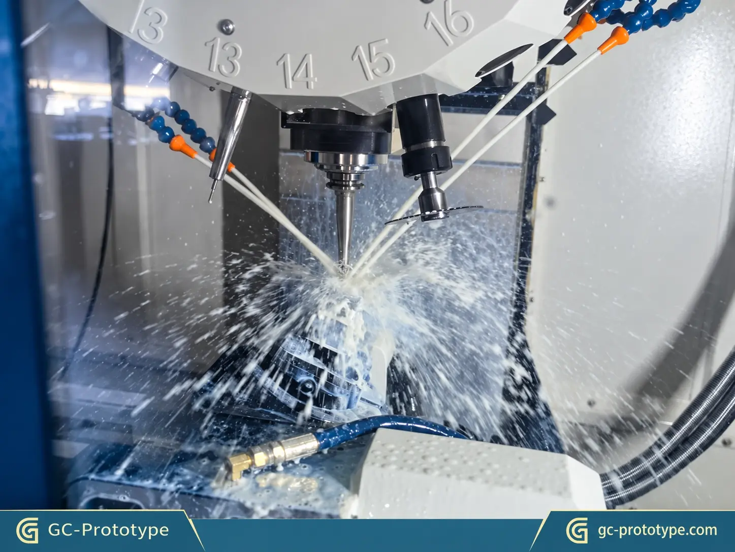
Metal prototype parts help engineers validate product designs, mechanical strength, dimensional accuracy, and assembly performance before investing in production tooling. Whether developing prototype metal parts for automotive systems, robotics, medical devices, or aerospace applications, choosing the right manufacturing process directly affects quality, cost, and lead time. Modern metal prototype fabrication includes CNC machining, CNC turning, sheet metal fabrication, metal 3D printing, and casting, each offering different advantages depending on geometry, material, quantity, and functional requirements.
During new product introduction (NPI), engineering teams must often evaluate multiple design iterations before selecting a final manufacturing method. A metal prototype may need to withstand actual mechanical loads, fit precisely into an assembly, resist corrosion, or operate under demanding temperatures.
Unlike appearance-only models, functional metal prototypes provide engineering data that can influence the success of the final product.
This guide explains how to choose manufacturing processes, compare metals, control tolerances, optimize DFM, estimate costs, and transition from prototype development to production.
For Mechanical Engineers, Product Development Engineers, Manufacturing Engineers, and Procurement Managers, understanding these factors helps reduce technical uncertainty and unnecessary manufacturing expenses.
GC Prototype supports customers throughout the development journey: CAD → Prototype Samples → Functional Validation → Low-Volume Pilot Production → Mass Production Support.
Metal prototype parts are physical components manufactured from metal materials to evaluate a product’s design, mechanical behavior, assembly compatibility, and manufacturability before production.
They may represent an individual component or part of a complete engineering assembly.
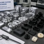
Common examples include:
CNC-machined aluminum housings
Stainless steel brackets
Precision metal shafts
Titanium structural components
Sheet metal enclosures
Prototype automotive components
Robotic actuator housings
The purpose of a prototype depends on the development stage.
A visual prototype primarily evaluates appearance, overall dimensions, and design proportions.
A functional prototype must perform under conditions representative of the intended application.
For example, a robotic joint housing may require accurate bearing seats and sufficient structural stiffness to withstand repeated torque loads.
Similarly, an electric vehicle component may need to survive vibration, thermal cycling, and mechanical assembly testing.
Functional prototypes therefore require careful control of:
Material properties
Dimensional tolerances
Surface finish
Mechanical strength
Assembly interfaces
Prototype validation allows engineers to identify manufacturing and design problems before significant tooling investment.
Typical objectives include checking fit, detecting assembly interference, measuring deformation, and evaluating mechanical reliability.
A prototype that fails during controlled testing can reveal weaknesses before they become expensive production problems.
However, prototypes must use appropriately representative materials and manufacturing methods. A CNC-machined aluminum prototype may not reproduce every property of a future die-cast component, even when the geometry is identical.
Understanding these differences helps engineers interpret test results correctly.
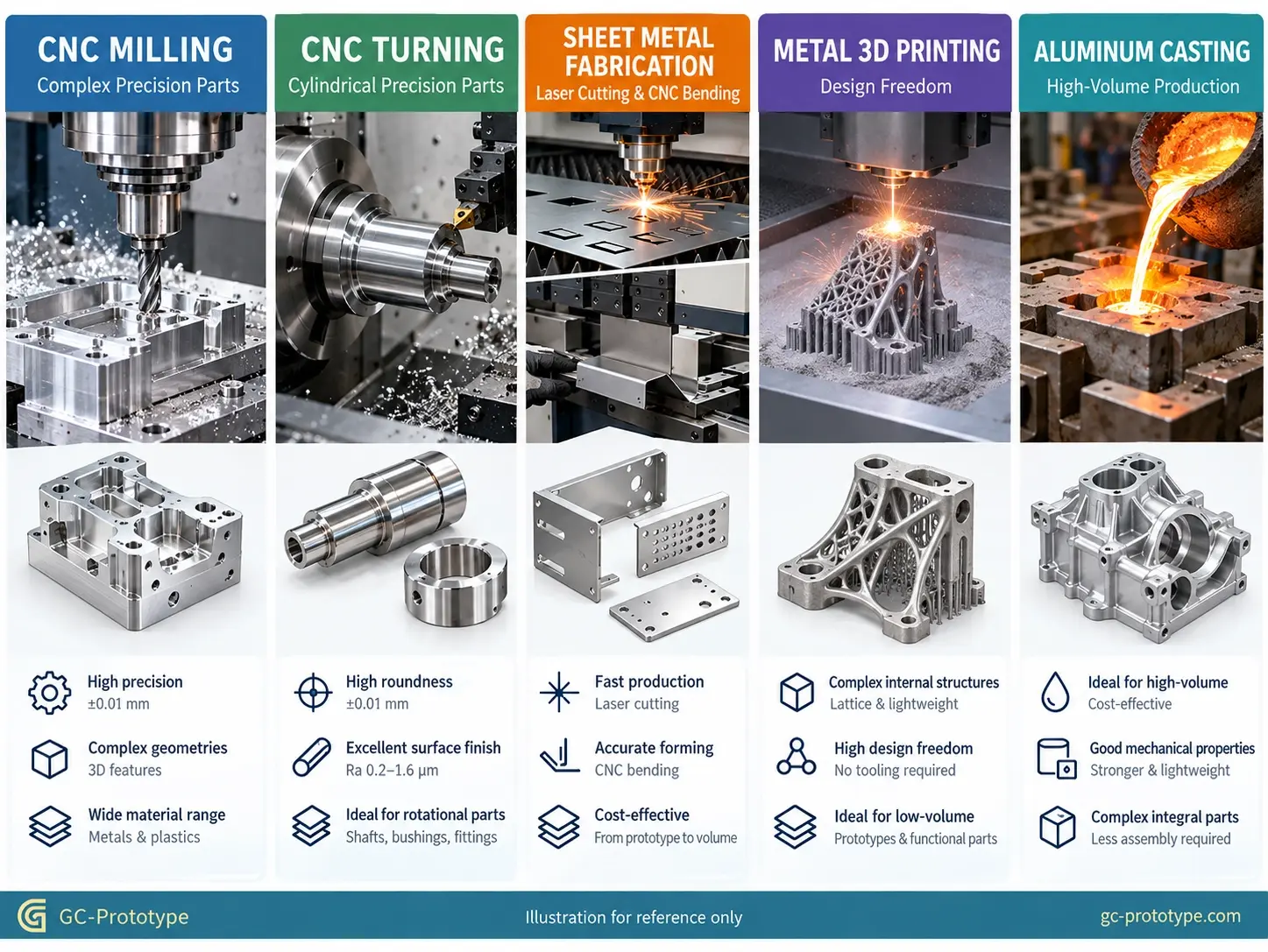
Metal prototype fabrication involves several manufacturing technologies, each suited to particular component geometries, materials, and development requirements.
The correct process should be selected according to the component’s intended function rather than its appearance alone.
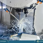
CNC machining is one of the most versatile processes for manufacturing precision metal prototypes.
Computer-controlled milling machines remove material from solid metal stock to create components based on a CAD model.
Typical applications include:
Aluminum equipment housings
Robotic joints
Automotive brackets
Medical instrument components
Aerospace structural parts
CNC milling is particularly effective for components requiring:
Accurate mounting interfaces
Precision holes
Flat sealing surfaces
Complex accessible cavities
Functional metal properties
Three-axis machines are suitable for many conventional geometries.
Five-axis machining provides additional flexibility when parts contain compound angles, curved surfaces, or features requiring access from several directions.
For functional testing, CNC machining can provide representative properties when the prototype uses the intended material grade and condition.
CNC turning is primarily used for rotationally symmetric components.
Typical products include shafts, pins, threaded connectors, bushings, and precision sleeves.
During turning, the workpiece rotates while cutting tools remove material.
Swiss-type CNC turning can provide additional advantages for small, slender components because the workpiece is supported close to the cutting zone.
This is particularly useful for miniature precision parts with demanding diameter and concentricity requirements.
Sheet metal fabrication is a strong choice when a component can be manufactured from relatively uniform-thickness metal stock.
Common operations include:
Laser cutting
CNC bending
Welding
Hardware insertion
Surface finishing
Typical applications include industrial equipment enclosures, electronic chassis, mounting brackets, and automotive covers.
For sheet metal prototypes, engineers should consider bend radii, flange lengths, hole-to-bend distances, and assembly access.
Poorly positioned holes near bends may distort during forming.
Metal additive manufacturing builds components layer by layer.
Processes such as laser powder bed fusion can produce complex structures that are difficult to manufacture using conventional CNC machining.
Examples include:
Internal lattice structures
Lightweight aerospace components
Complex fluid channels
Topology-optimized parts
However, metal additive manufacturing may require heat treatment, support removal, surface finishing, and secondary machining.
Functional performance depends on the material, build orientation, processing parameters, and post-processing conditions.
Casting becomes attractive when engineers need to evaluate components intended for eventual high-volume production.
Potential applications include motor housings, structural brackets, and complex aluminum enclosures.
Prototype casting may help validate near-production geometry, but tooling investment and design changes can increase initial cost.
For early development, CNC machining often provides greater flexibility.
| Manufacturing Process | Main Advantage | Limitations | Best Applications |
| CNC Milling | High precision and design flexibility | Limited internal tool access | Housings, brackets, functional parts |
| CNC Turning | Efficient cylindrical machining | Primarily rotational geometry | Shafts, pins, bushings |
| Sheet Metal Fabrication | Efficient thin-wall structures | Bend and forming limitations | Enclosures, brackets, chassis |
| Metal 3D Printing | Complex internal geometry | Post-processing often required | Lattices, complex channels |
| Casting | Efficient near-net-shape production | Tooling investment | Housings, production validation |
The ideal manufacturing strategy may combine several processes rather than relying on only one.
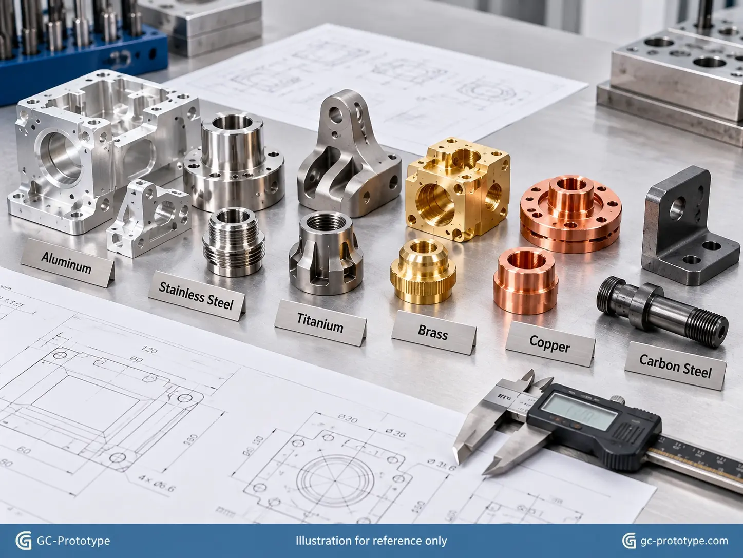
Material selection directly influences mechanical performance, machining cost, corrosion resistance, and prototype reliability.
When evaluating prototype metal parts, engineers should consider the intended loading conditions, environmental exposure, mass requirements, and final production material.
Aluminum is widely used in product development because it combines low density, good machinability, and useful mechanical performance.
6061 aluminum is frequently selected for:
Electronics housings
Robotic components
Automotive prototypes
Industrial equipment
7075 aluminum provides higher strength and is commonly considered for demanding lightweight structural applications.
However, 7075 is generally more expensive and may offer less corrosion resistance in certain environments.
Engineers should select the alloy according to functional requirements rather than strength alone.
Stainless steel offers good mechanical strength and corrosion resistance.
304 stainless steel is frequently used for general industrial equipment.
316 stainless steel may be preferable when enhanced resistance to certain corrosive environments is required.
Typical applications include:
Mechanical fixtures
Fluid-handling components
Medical equipment
Industrial assemblies
Exact material grades and surface conditions should match the intended application.
Titanium alloys provide high strength-to-weight performance and excellent corrosion resistance in suitable applications.
They are frequently considered for aerospace, medical, and advanced robotic components.
However, titanium machining requires careful heat management and appropriate cutting tools.
Its higher material and machining costs mean it should be selected when performance requirements justify the investment.
Carbon steel is attractive for structural strength and cost-sensitive mechanical components.
Brass offers good machinability and is useful for fittings and connectors.
Copper provides excellent thermal and electrical conductivity, making it attractive for heat-transfer and electrical components.
| Material | Main Advantage | Relative Machining Cost | Typical Applications |
| Aluminum 6061 | Lightweight, versatile | Low–Medium | Housings, brackets |
| Aluminum 7075 | High strength | Medium | Structural components |
| Stainless Steel 304 | Corrosion resistance | Medium | Industrial equipment |
| Stainless Steel 316 | Enhanced corrosion resistance | Medium–High | Fluid and medical equipment |
| Titanium Alloy | Strength-to-weight performance | High | Aerospace, medical |
| Carbon Steel | Strength and economy | Low–Medium | Mechanical structures |
| Brass | Excellent machinability | Low–Medium | Fittings, connectors |
| Copper | Thermal/electrical conductivity | Medium–High | Electrical and thermal parts |
Cost classifications are relative and vary by material grade, geometry, stock availability, and supplier.
For engineering validation, using the specified production-intent material is often more important than choosing the least expensive material.
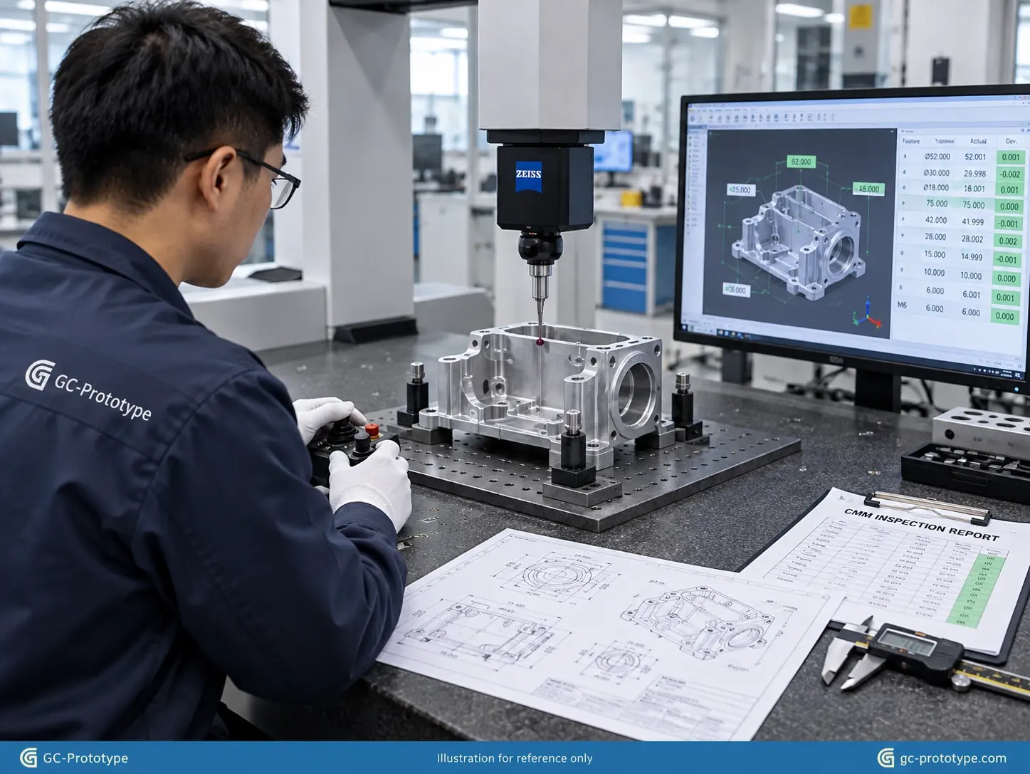
Dimensional accuracy plays an important role in functional metal prototype manufacturing.
However, not every component feature requires the same tolerance.
Typical functional interfaces may include bearing bores, positioning holes, sealing surfaces, and precision sliding features.
General CNC machining tolerances depend on component geometry, material, machine capability, and inspection strategy.
For selected critical features, tolerances around ±0.01 mm may be achievable under suitable conditions.
More demanding requirements may be possible but should be confirmed with the manufacturing supplier.
General tolerance standards such as ISO 2768 can help define dimensions without individual tolerance callouts, while critical geometric requirements should be specified explicitly.
Surface finishing can improve corrosion resistance, appearance, or functional performance.
Common options include:
Bead blasting
Anodizing
Hard anodizing
Electropolishing
Passivation
Powder coating
The correct finish depends on material and intended use.
For example, hard anodizing may improve wear resistance on suitable aluminum components, while stainless steel passivation can help maintain corrosion resistance when appropriately specified.
Finishing requirements should be established before quotation because coating thickness and additional processing can affect dimensions and cost.
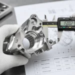
Coordinate Measuring Machines can verify complex geometric relationships such as hole position, flatness, and profile.
A complete inspection strategy may include:
Dimensional measurement
Surface roughness verification
Thread inspection
Material certification
Assembly testing
For B2B engineering projects, supplying a properly defined drawing with critical GD&T requirements improves communication between the design team and manufacturer.
The cost of manufacturing metal prototypes depends on material, geometry, quantity, machining time, tolerances, and finishing requirements.
For procurement teams, comparing quotation prices without considering these factors can lead to misleading conclusions.
The total manufacturing cost typically includes:
Raw material
CAD/CAM programming
Machine setup
Cutting time
Tool consumption
Inspection
Finishing
Packaging
A simple aluminum bracket may be relatively inexpensive to manufacture.
A titanium component with deep cavities, extremely tight tolerances, and complex finishing requirements may cost substantially more.
Material utilization also matters.
If a small finished component requires a much larger block of raw stock, material waste can increase total cost.
CNC machining typically includes fixed setup and programming costs.
These costs are distributed across the total quantity.
Consider a hypothetical project with:
Setup and programming: $220
Variable manufacturing cost: $75 per part
| Prototype Quantity | Total Cost | Average Unit Cost |
| 1 | $295 | $295.00 |
| 10 | $970 | $97.00 |
| 50 | $3,970 | $79.40 |
| 100 | $7,720 | $77.20 |
Illustrative cost calculation only. These figures are not actual GC Prototype quotations. Inspection, finishing, shipping, and other project costs may vary.
The example demonstrates why average unit costs often decrease as quantity increases.
However, the exact relationship depends on setup complexity, material costs, and machining efficiency.
CNC machining often provides competitive pricing for parts with accessible geometry and relatively simple material-removal requirements.
Metal 3D printing may become attractive when a component contains complex internal structures or would require excessive material removal through machining.
The best process depends on total manufacturing cost, including required post-processing.
For early prototypes, CNC machining avoids dedicated casting or molding tooling.
At higher volumes, production tooling may reduce unit costs.
The crossover depends on:
Expected annual quantity
Tooling investment
Part complexity
Manufacturing cycle time
Secondary operations
Therefore, engineers should consider both initial prototype cost and future production economics before finalizing the design.
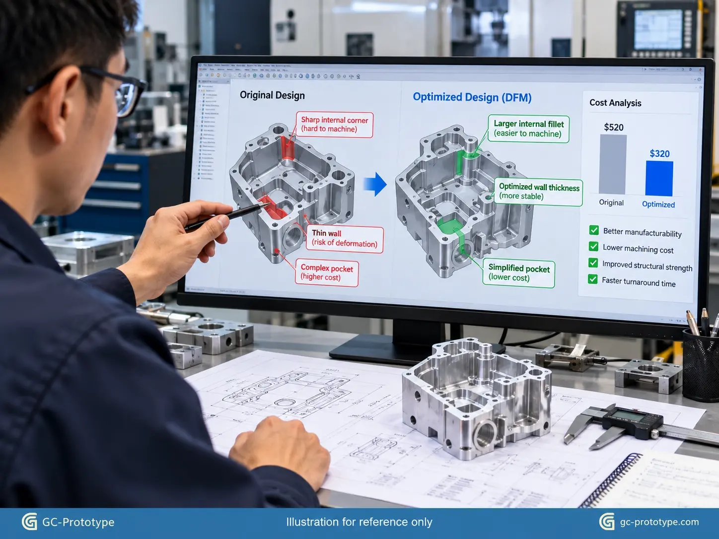
Design for Manufacturability (DFM) helps engineers identify opportunities to reduce machining time, material waste, and manufacturing complexity.
A component may be technically machinable but unnecessarily expensive because of avoidable design decisions.
Small internal corner radii require small cutting tools.
Small tools often remove material more slowly and can increase deflection or machining time.
Where functional requirements allow, larger internal radii improve tool accessibility.
Wall thickness is equally important.
Thin aluminum or steel structures may vibrate during machining or distort after unclamping.
Maintaining practical wall thickness can improve dimensional consistency and reduce scrap.
Over-tolerancing is a common cause of excessive prototype cost.
A critical bearing interface may require tight dimensional control, while an exterior cosmetic surface may not.
Engineers should use GD&T to identify the features that directly affect assembly and function.
Applying demanding tolerances only where necessary reduces machining and inspection effort.
Designing around commonly available stock sizes can improve material utilization.
Engineers can also reduce machining costs by:
Avoiding unnecessary deep cavities
Improving cutter access
Reducing complex undercuts
Combining compatible features
Simplifying workholding
For complex prototypes, early collaboration between design engineers and manufacturing specialists can prevent costly redesigns.
The ideal prototype design should also consider the intended production process.
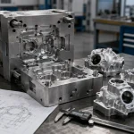
For example, a CNC-machined housing may eventually be die cast.
During prototype development, engineers can begin evaluating:
Draft angles
Wall thickness
Fillets
Parting lines
Secondary machining requirements
This reduces the risk of discovering major manufacturability problems after the functional design has been approved.
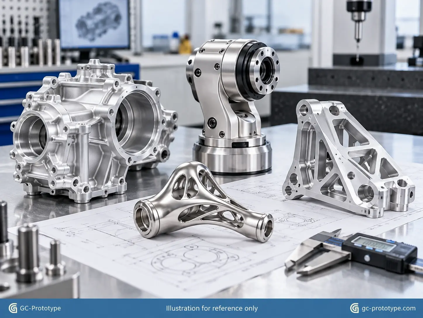
Precision metal prototypes support product development across numerous industries.
Automotive engineers use metal prototypes to evaluate motor housings, transmission brackets, battery cooling plates, and structural components.
Functional testing may include vibration, thermal cycling, and assembly verification.
CNC-machined aluminum prototypes are particularly useful for validating precision powertrain interfaces.
Robotics manufacturers require lightweight, rigid components with accurate mechanical interfaces.
Common applications include:
Robotic joint housings
Actuator brackets
Precision linkages
Sensor mounting structures
Metal prototypes allow engineering teams to evaluate stiffness, fit, and dynamic performance before production.
Medical-device developers use precision metal prototypes for surgical instruments, diagnostic equipment, and mechanical assemblies.
Material selection and inspection requirements depend on the intended device use.
Certain projects may require additional documentation, traceability, or validated processing.
Aerospace prototypes may include brackets, lightweight housings, structural connectors, and precision interfaces.
Engineers frequently prioritize strength-to-weight performance and dimensional accuracy.
Prototype testing can provide valuable information about assembly, stiffness, and mechanical behavior before production.
A successful prototype program should connect engineering development with future manufacturing requirements.
GC Prototype supports customers across the complete product-development lifecycle.
The engineering team defines geometry, materials, critical tolerances, and functional requirements.
A DFM review identifies manufacturing challenges before physical production begins.
CNC machining, turning, sheet metal fabrication, or other suitable technologies produce physical prototype parts.
These components allow engineers to verify mechanical fit and assembly compatibility.
Representative prototypes undergo relevant engineering tests, which may include mechanical loading, vibration, temperature exposure, or assembly cycling.
The objective is to identify design weaknesses before later-stage production investment.
Pilot quantities help evaluate manufacturing consistency, inspection requirements, assembly workflow, and production cost.
Once the design is stable, manufacturing processes can be optimized for volume, quality, and cost.
Depending on the component, production may continue with CNC machining or transition to casting, molding, or another scalable process.
This integrated approach helps reduce unnecessary supplier transitions and maintain manufacturing continuity.
A complete Request for Quotation (RFQ) helps manufacturers evaluate project requirements accurately.
For custom metal prototypes, buyers should provide:
3D CAD model: STEP or another compatible engineering format.
2D drawing: Critical dimensions, GD&T, and technical notes.
Material specification: Exact alloy and condition.
Quantity: Required prototype units and expected future volumes.
Surface finish: Functional or cosmetic finishing requirements.
Inspection requirements: Dimensional reports or other documentation.
Delivery expectations: Required manufacturing schedule.
Where future mass production is planned, providing estimated annual volumes can help suppliers recommend a more suitable manufacturing strategy.
Metal prototype parts are physical metal components manufactured to evaluate product geometry, assembly, strength, and functional performance before production.
They can be made using CNC machining, turning, sheet metal fabrication, metal 3D printing, and other manufacturing processes.
The best method depends on geometry, material, quantity, tolerance requirements, and intended function.
CNC machining is often suitable for precision functional components, while sheet metal fabrication is efficient for thin-wall structures. Metal 3D printing is useful for highly complex geometries.
Neither method is universally better.
CNC machining is particularly effective for precision interfaces and components made from solid stock.
Metal 3D printing provides advantages for complex internal geometries and lightweight lattice structures.
Common materials include aluminum, stainless steel, carbon steel, titanium, brass, and copper.
Material selection depends on strength, weight, corrosion resistance, thermal performance, and cost.
Tolerance capability depends on part geometry, material, machine accuracy, and inspection.
Selected critical features can achieve tight tolerances under appropriate conditions, while general geometry may use broader manufacturing tolerances.
Cost depends on material, quantity, complexity, tolerances, machining time, inspection, and finishing.
A simple aluminum prototype may cost substantially less than a complex titanium component requiring multiple setups and demanding inspection.
Lead time depends on material availability, complexity, quantity, finishing, and inspection requirements.
Simple components may be manufactured within several working days, while complex projects can take longer.
Yes.
CNC machining supports prototype and low-volume production, while higher-volume manufacturing may use casting, forming, or other scalable processes.
Engineers should consider future production requirements during early DFM to minimize redesign.
Successful metal prototyping requires the right combination of manufacturing technology, material selection, dimensional accuracy, and cost control.
High-quality metal prototype parts allow engineering teams to verify product performance before committing to expensive production tooling.
By choosing suitable processes for prototype metal parts, engineers can balance mechanical reliability, manufacturing complexity, and development speed.
Effective metal prototype fabrication also depends on early DFM optimization, realistic tolerances, appropriate material selection, and clear communication between engineering and procurement teams.
For companies developing new products, integrating prototype manufacturing with functional validation and production planning can reduce unnecessary design iterations and improve manufacturing readiness.
GC Prototype supports customers throughout the complete development journey:
CAD → Prototype Samples → Functional Validation → Low-Volume Pilot Production → Mass Production Support
Ready to transform your CAD designs into precision metal prototype parts?
Whether you are a Mechanical Engineer developing complex functional components or a Sourcing Manager comparing CNC machining, sheet metal fabrication, and metal 3D printing, GC Prototype provides engineering-focused manufacturing support.
Our services help companies validate designs, optimize manufacturability, and prepare products for scalable production.