Address:
Shenzhen Bao'an District Xinqiao Subdistrict Huangpu Community Huangpu East Ring Road No. 504 Shenzhen Yuan Industrial City Building C
Work Hours:
Monday to Friday: 9AM - 21PM
Weekend: 9AM - 21PM

Address:
Shenzhen Bao'an District Xinqiao Subdistrict Huangpu Community Huangpu East Ring Road No. 504 Shenzhen Yuan Industrial City Building C
Work Hours:
Monday to Friday: 9AM - 21PM
Weekend: 9AM - 21PM

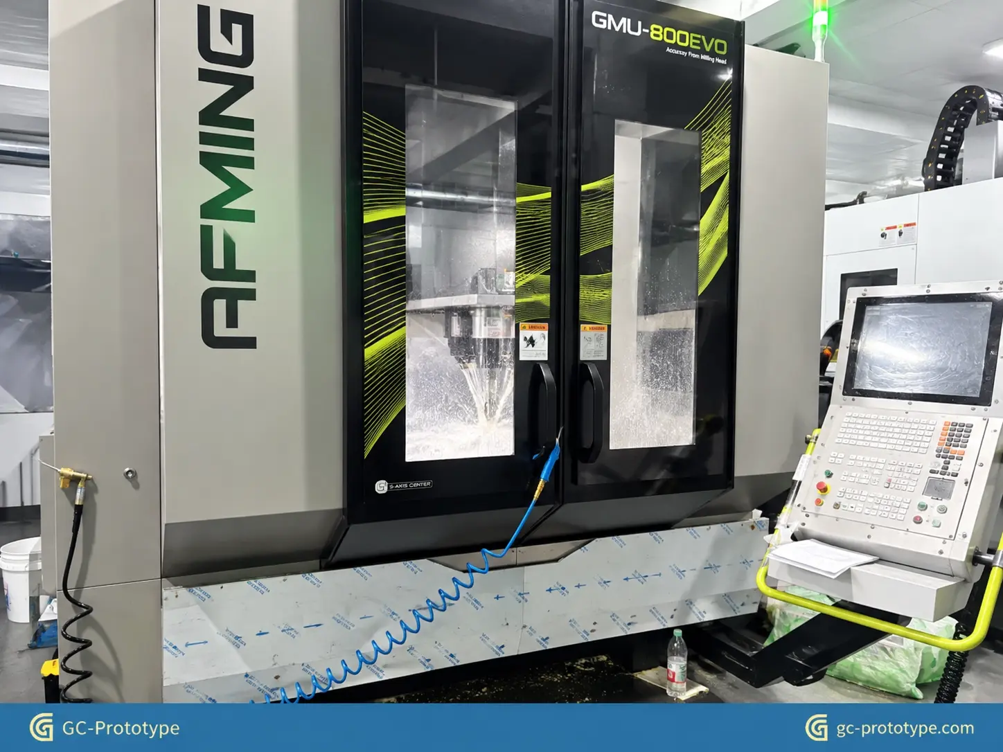
Prototype machining transforms engineering CAD models into functional metal and plastic components used to evaluate product designs before full-scale production. For engineers and product development teams, CNC machined prototypes provide a practical way to verify dimensional accuracy, material performance, mechanical fit, and assembly functionality using production-representative materials.
However, successful machining prototypes requires more than converting a CAD file into a finished part. Material selection, machining accessibility, dimensional tolerances, surface finishes, and inspection requirements all influence the final cost and performance.
This guide explains how CNC prototype machining works, when to use it, which materials to consider, how to control manufacturing costs, and what engineers should prepare before requesting a quotation.
Prototype machining is a subtractive manufacturing process that uses cutting tools to remove material from solid metal or plastic stock, producing physical components based on digital engineering designs.
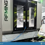
Computer Numerical Control (CNC) machines execute programmed toolpaths to create features such as holes, slots, pockets, threads, mounting surfaces, and complex three-dimensional geometries.
Unlike prototypes produced primarily for visual evaluation, CNC-machined components can support mechanical testing, dimensional inspection, and functional assembly verification.
The process typically begins with a 3D CAD model. Engineers or manufacturing specialists review the geometry, select a suitable material, and develop machining programs using CAM software.
The workpiece is secured in a fixture or machine vise while CNC cutting tools remove material in controlled operations.
Depending on the geometry, manufacturers may use CNC milling, turning, drilling, tapping, or multi-axis machining.
After machining, the component may undergo deburring, surface finishing, and dimensional inspection.
The resulting prototype helps engineering teams identify design problems before investing in production tooling.
Appearance prototypes primarily evaluate external geometry, visual design, ergonomics, and presentation quality.
Functional prototypes must often withstand mechanical loads, temperature changes, repeated assembly, or environmental exposure.
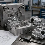
For example, a robot joint housing may require accurate bearing seats, threaded mounting holes, and controlled alignment between mating components.
A visual prototype may represent these features, but a CNC-machined aluminum part can also be used for realistic mechanical testing.
This distinction helps engineers decide whether CNC machining or another rapid prototyping method is more appropriate.
CNC machining is particularly useful when the prototype must closely represent the mechanical behavior of the intended production material.
Common reasons for selecting CNC machining include functional testing, assembly validation, accurate interfaces, and material-specific performance evaluation.
Functional testing often requires reliable dimensional relationships between critical features.
For example, a precision actuator housing may contain bearing pockets, alignment holes, sealing surfaces, and threaded connections.
CNC machining allows engineers to create these features in real engineering materials, making the prototype suitable for evaluating assembly fit, stiffness, and mechanical operation.
Machining can also help identify potential problems such as insufficient wall stiffness, inaccessible fasteners, or excessive tolerance accumulation.
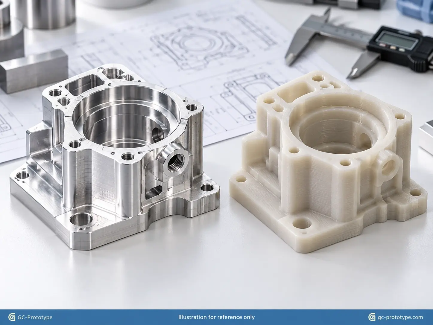
CNC machining and additive manufacturing serve different engineering needs.
3D printing is often advantageous for complex internal channels, lightweight lattice structures, and rapid geometric exploration.
CNC machining is frequently preferred when material consistency, precision interfaces, surface finish, or mechanical testing using specified wrought materials are important.
| Evaluation Factor | CNC Prototype Machining | 3D Printing |
| Manufacturing method | Material removal | Layer-by-layer material addition |
| Material options | Engineering metals and plastics | Process-specific polymers and metals |
| Complex internal geometry | Limited by tool accessibility | Often advantageous |
| Precision mating surfaces | Strong capability with proper process control | May require secondary machining |
| Functional material testing | Useful for specified stock materials | Depends on printing process and material |
| Design changes | Requires revised machining operations | Often convenient for rapid iterations |
| Main cost drivers | Setups, machining time, material and inspection | Build volume, supports, material and post-processing |
Neither process is universally better.
Engineers should evaluate geometry, material requirements, quantities, tolerances, and testing objectives before selecting the manufacturing method.
A structured manufacturing workflow helps reduce dimensional errors, unnecessary machining operations, and unexpected production delays.
Engineers typically submit a 3D CAD file in STEP format or another supported neutral file format.
A separate 2D technical drawing is valuable when the component includes critical tolerances, GD&T requirements, threads, surface finishes, or inspection notes.
Before programming begins, the manufacturer evaluates the design for manufacturability (DFM).
Typical questions include whether cutting tools can reach the required features, whether walls are sufficiently rigid, and whether tight tolerances are necessary across the entire component.
Identifying these issues early can prevent expensive design changes after machining.
CNC milling is commonly used for housings, brackets, plates, pockets, and other prismatic components.
CNC turning is especially suitable for rotational components such as shafts, bushings, threaded adapters, and cylindrical fittings.
For complex geometry, 5-axis CNC machining can improve tool accessibility and reduce the number of repositioning operations.
However, 5-axis machining is not automatically more economical. Simple components may be produced more efficiently using conventional 3-axis equipment.
The correct approach depends on part geometry, fixturing requirements, quantity, and dimensional relationships.
After machining, parts may undergo deburring, polishing, bead blasting, anodizing, passivation, or other finishing operations, depending on the material and application.
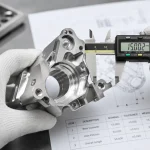
Inspection methods may include digital calipers, micrometers, bore gauges, height gauges, and coordinate measuring machines (CMMs).
Critical dimensions should be checked against the approved engineering drawing rather than relying only on the visual appearance of the finished prototype.
For functional assemblies, inspection should prioritize features that affect alignment, sealing, bearing fit, and mechanical performance.
Material selection directly influences prototype performance, machining efficiency, inspection requirements, and cost.
Engineers should select a material based on the intended testing conditions rather than choosing only the lowest-cost stock.
Aluminum 6061 is widely used for prototype housings, brackets, mechanical fixtures, and structural components.
It offers a useful combination of machinability, corrosion resistance, availability, and mechanical performance.
Aluminum 7075 generally provides higher strength than 6061 in commonly specified tempers, making it suitable for some highly loaded lightweight components.
However, 7075 is not automatically the best choice. Engineers should evaluate corrosion requirements, joining methods, cost, and the applicable material condition.
Stainless steel is useful when components require corrosion resistance, mechanical strength, or durability under demanding operating conditions.
Its machining behavior varies considerably between grades.
Titanium alloys provide high specific strength and corrosion resistance, making them important in selected aerospace and medical applications.
However, titanium machining requires careful consideration of tool wear, heat generation, cutting parameters, and manufacturing cost.
For medical-related parts, material grade selection and regulatory suitability must be evaluated separately from basic machining capability.
Engineering plastics are useful for lightweight structural parts, electrical housings, bushings, fixtures, and functional prototype assemblies.
| Material | Common Prototype Applications | Main Considerations |
| Aluminum 6061 | Housings, brackets, fixtures | Versatile and generally economical |
| Aluminum 7075 | Lightweight, highly loaded parts | Higher material cost; application-dependent corrosion considerations |
| Stainless Steel | Shafts, fittings, precision components | Grade selection and machining time |
| Titanium | Lightweight precision and selected medical components | Tool wear and machining cost |
| ABS | Enclosures and functional plastic parts | Heat resistance and dimensional behavior |
| POM (Acetal) | Bushings, gears and sliding components | Thermal expansion and part geometry |
| Polycarbonate | Protective and mechanical housings | Residual stress and machining-related damage |
| PEEK | High-performance mechanical components | Material cost and temperature management |
For CNC machined prototypes, the selected stock grade should reflect the actual performance requirements of the project.
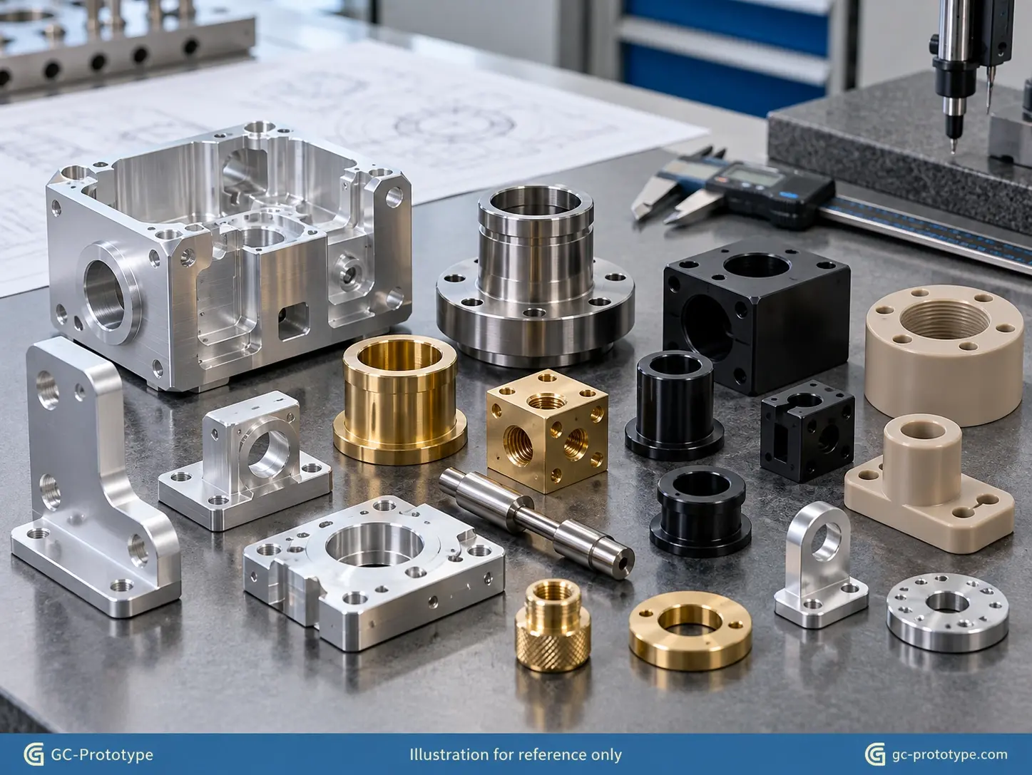
Dimensional accuracy is one of the most important considerations in functional prototype machining.
However, specifying unnecessarily tight tolerances can increase machining time, inspection effort, and manufacturing cost.
Not every dimension requires the same level of precision.
A clearance feature or noncritical exterior surface may tolerate greater dimensional variation than a bearing bore or precision locating interface.
For example, an engineering drawing might specify a general tolerance of ±0.10 mm for suitable noncritical dimensions while assigning a tighter requirement to a functional feature.
These values are illustrative rather than universal manufacturing capabilities. Achievable tolerances depend on material, geometry, equipment, process control, and inspection methods.
A practical strategy is to identify critical-to-function features and apply tighter requirements only where necessary.
Geometric Dimensioning and Tolerancing (GD&T) helps communicate requirements for position, flatness, perpendicularity, concentricity-related controls, and other geometric relationships.
Appropriate datums are especially important for parts containing multiple mating features.
Surface roughness may also affect performance.
For example, sealing interfaces, sliding surfaces, and bearing contact regions may require different surface conditions from cosmetic exterior surfaces.
Engineers should define the functional requirements clearly and discuss feasible measurement methods with the manufacturer before production.
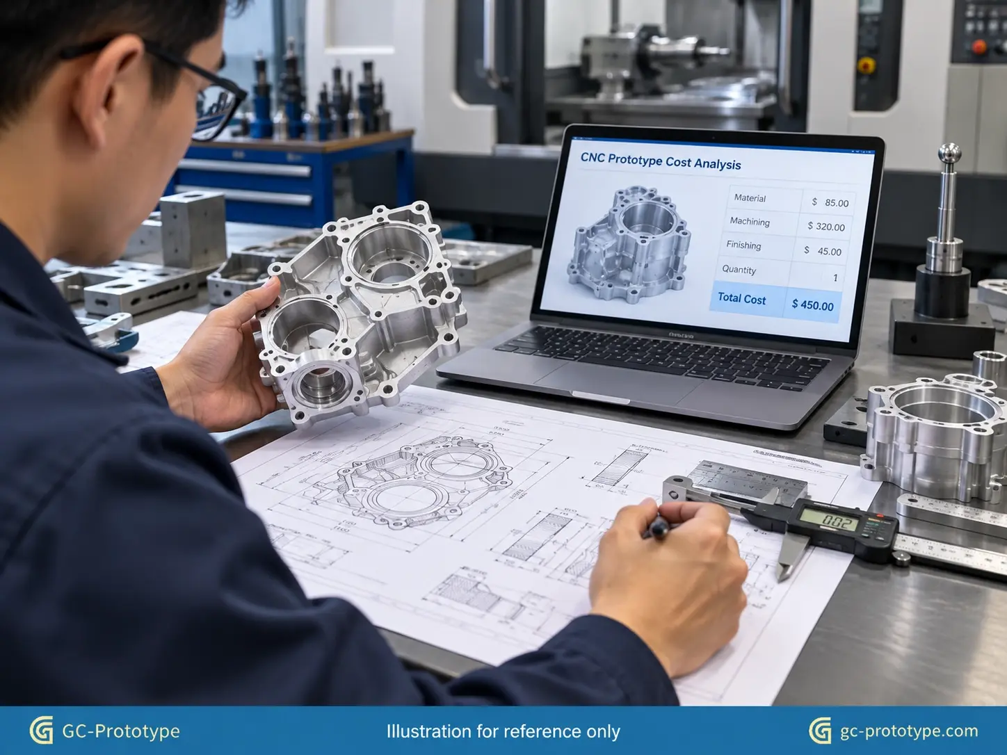
The cost of prototype machining is influenced by several interconnected factors rather than material price alone.
Major cost drivers include design complexity, machine setup, cutting time, material utilization, finishing requirements, inspection, and order quantity.
Material prices vary significantly between aluminum, stainless steel, titanium, and engineering plastics.
Geometry can have an equally important effect on manufacturing cost.
Deep pockets, narrow slots, inaccessible internal corners, and multiple machining orientations may require longer tools, special fixtures, or additional setup operations.
Manufacturers also account for CAD review, CAM programming, fixture preparation, and machine setup.
These activities create fixed costs that may be substantial for a one-piece prototype.
Prototype machining often becomes more economical per unit when several identical components are produced in one batch.
This happens because programming and setup costs can be distributed across multiple parts.
A simplified cost model is:
Total Cost = Setup and Programming + Material + Machining + Finishing + Inspection
The exact balance depends on the project.
For example, increasing an order from one piece to ten pieces may reduce the setup cost allocated to each component, although material and machining expenses still increase with total quantity.
Therefore, engineers should request quotations for realistic quantities rather than assuming every additional part will have the same unit price.
Design for Manufacturability can reduce manufacturing expenses without compromising essential functionality.
Potential improvements include using standardized hole sizes, simplifying difficult-to-machine features, reducing unnecessary surface finishing, and avoiding excessively strict tolerances.
It can also be useful to compare several manufacturing strategies.
A housing that requires multiple setups on a 3-axis machine may be more economical on a 5-axis machine—or vice versa—depending on its complexity and production quantity.
Good DFM decisions improve manufacturability, reduce machining risk, and help prototypes meet functional requirements.
Very thin walls may deform under cutting forces or vibration, particularly when the workpiece lacks sufficient support.
Appropriate wall thickness depends on material, component size, toolpath strategy, and fixturing.
Internal corners also require consideration.
Standard rotary cutting tools cannot create perfectly sharp internal corners in conventional milling operations.
Adding suitable corner radii can improve tool accessibility and reduce the need for very small cutters.
Deep pockets and narrow cavities can require long cutting tools that are more susceptible to deflection and vibration.
Where the design permits, reducing unnecessary pocket depth or increasing tool clearance may improve machining efficiency.
Blind holes also require adequate depth allowances for drills, taps, and other tools.
Engineers should distinguish between thread depth and total drilled-hole depth when preparing drawings.
Each workpiece repositioning operation introduces additional setup time and may create opportunities for dimensional variation.
Where feasible, grouping features into accessible machining orientations can improve efficiency.
For complex components, multi-axis machining or optimized fixturing may reduce repositioning requirements.
However, design simplification should never compromise critical load paths, assembly accuracy, sealing performance, or safety requirements.
The best DFM solution balances manufacturing efficiency with functional performance.
Prototype machining supports product development across industries that require accurate functional components.
Robotics applications commonly include actuator housings, robotic joint components, grippers, sensor mounts, brackets, and precision mechanical interfaces.
CNC machined prototypes can help engineering teams evaluate bearing alignment, mechanical clearance, structural stiffness, and assembly repeatability before finalizing production designs.
Medical device development may require prototype instrument housings, positioning components, mechanical assemblies, and precision equipment parts.
Material selection, dimensional control, cleaning requirements, and traceability should be evaluated according to the intended application.
Prototype machining alone does not establish medical-device compliance or biocompatibility.
Automotive prototype components may include transmission housings, mounting brackets, sensor fixtures, and lightweight structural parts.
Aerospace engineering teams may use machined prototypes to evaluate assembly interfaces, mechanical designs, and selected test hardware.
In all cases, inspection requirements should reflect the functional and project-specific specifications.
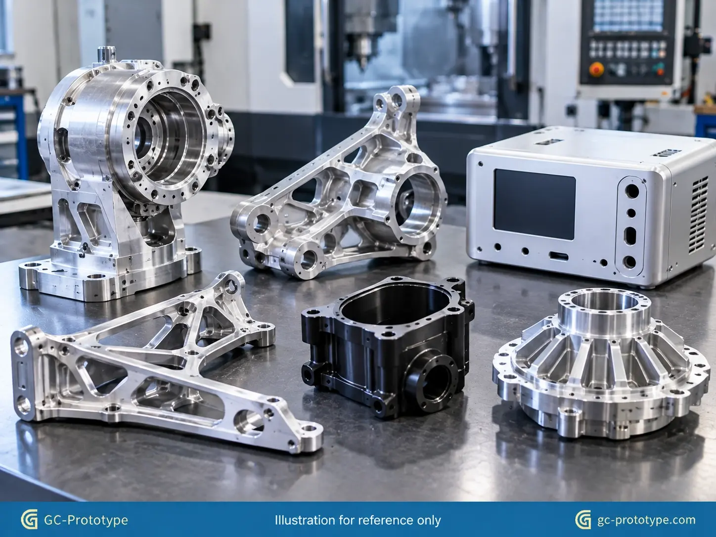
A complete Request for Quotation (RFQ) helps manufacturers evaluate the project accurately and respond with appropriate pricing and manufacturing recommendations.
Start with an accurate 3D CAD model and a technical drawing where necessary.
The drawing should identify functional dimensions, critical tolerances, threads, surface finish requirements, and inspection notes.
Specify the required material grade and condition, rather than using broad descriptions such as “aluminum” or “engineering plastic.”
When material alternatives are acceptable, communicate that flexibility to the manufacturer.
Before requesting a quote, engineers and purchasing teams should prepare:
1.CAD files: STEP files or another supported 3D format.
2.Engineering drawings: Critical dimensions, GD&T, threads, and surface requirements.
3.Material specifications: Grade, temper or condition, where applicable.
4.Quantities: Current prototype requirement and possible repeat batches.
5.Finishing requirements: Anodizing, passivation, bead blasting, polishing, or other specified treatments.
6.Inspection requirements: Dimensional reports, material documentation, or other project-specific records.
7.Delivery information: Required date, destination, and packaging considerations.
Providing this information early can reduce clarification cycles and help avoid quotation changes caused by missing requirements.
Prototype machining focuses on producing parts for design verification, functional testing, and engineering development.
Production machining prioritizes repeatability, manufacturing efficiency, and consistent quality over larger quantities.
Both processes may use similar CNC equipment, but their fixturing, programming, inspection, and cost strategies can differ.
Accuracy depends on material, geometry, machining equipment, fixturing, and process control.
Precision features may require tighter tolerances than general exterior dimensions.
Engineers should identify critical dimensions and confirm achievable tolerances with the manufacturer before ordering.
Cost depends on material, geometry, quantity, setup requirements, tolerances, machining time, finishing, and inspection.
Simple aluminum parts are often more economical than highly complex titanium components, although actual prices must be evaluated through a project-specific quotation.
CNC machining is often advantageous when specified engineering materials, precision interfaces, and representative mechanical performance are important.
3D printing may be preferable for complex internal geometries, rapid design iterations, or structures that are difficult to machine.
The correct choice depends on the intended testing requirements.
A 3D CAD model is normally the starting point.
A 2D technical drawing is recommended when the design contains critical tolerances, threaded features, surface finish requirements, or other specifications not fully communicated in the CAD model.
Providing quantity, material, and delivery requirements also helps manufacturers prepare accurate quotations.
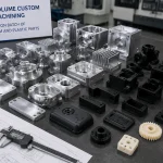
Yes. CNC machining can support one-off prototypes, engineering validation batches, and low-volume production.
For repeat orders, manufacturers may improve efficiency through revised fixturing, optimized toolpaths, and more consistent production planning.
The most economical manufacturing process should be evaluated against part complexity, quantity, material, and required consistency.
Successful prototype machining requires more than machining equipment. Engineers need clear communication, practical DFM support, appropriate material selection, reliable dimensional inspection, and a manufacturing process aligned with product development goals.
When evaluating a supplier, consider its experience with similar geometries, willingness to review engineering drawings, ability to explain manufacturing trade-offs, and approach to quality verification.
For international engineering and purchasing teams, transparent quotations and clearly documented manufacturing requirements can help reduce uncertainty during prototype development.
GC-Prototype provides custom CNC machining and rapid prototyping services for engineers developing functional components across robotics, automotive, medical equipment, aerospace, and industrial applications.
Whether you need an aluminum housing, a precision-machined mechanical component, or a small batch of prototype parts, sharing complete CAD files and project requirements is the best starting point for a productive manufacturing review.
Ready to turn your CAD design into a functional prototype?