Address:
Shenzhen Bao'an District Xinqiao Subdistrict Huangpu Community Huangpu East Ring Road No. 504 Shenzhen Yuan Industrial City Building C
Work Hours:
Monday to Friday: 9AM - 21PM
Weekend: 9AM - 21PM

Address:
Shenzhen Bao'an District Xinqiao Subdistrict Huangpu Community Huangpu East Ring Road No. 504 Shenzhen Yuan Industrial City Building C
Work Hours:
Monday to Friday: 9AM - 21PM
Weekend: 9AM - 21PM

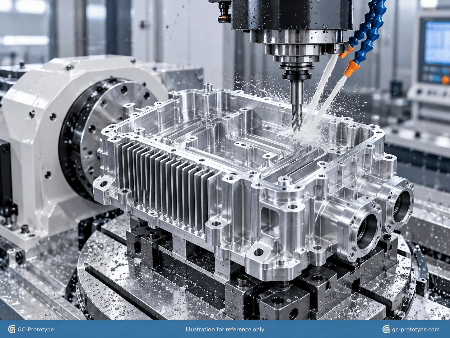
ISO 2768 tolerances for automotive cnc machining play an important role in developing reliable engine, transmission, chassis, and electric vehicle components. During automotive new product introduction (NPI), even small dimensional deviations can contribute to abnormal vibration, noise, sealing leakage, premature wear, or assembly difficulties. For engineering teams evaluating custom cnc machining for automotive prototypes, precision is not simply about achieving the tightest possible dimensions—it is about controlling critical features while balancing material performance, manufacturing efficiency, development time, and cost.
Automotive components operate under demanding conditions, including high rotational speeds, repeated vibration, temperature fluctuations, and dynamic mechanical loads.
An incorrectly sized bearing bore can affect assembly interference. Poor mounting-surface flatness may cause sealing problems. Excessive geometric variation in an electric drive housing can influence shaft alignment and noise, vibration, and harshness (NVH).
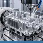
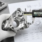
Precision CNC milling and turning help automotive engineers validate these critical relationships before committing to production tooling.
This guide explains automotive tolerance standards, GD&T, lightweight aluminum machining, electric vehicle applications, rapid prototyping, CNC versus die casting, and practical DFM strategies. It also examines the complete development process from CAD → prototype samples → functional validation → low-volume pilot production → mass production support.
Modern automotive systems require thousands of mechanical components to function together under demanding operating conditions.
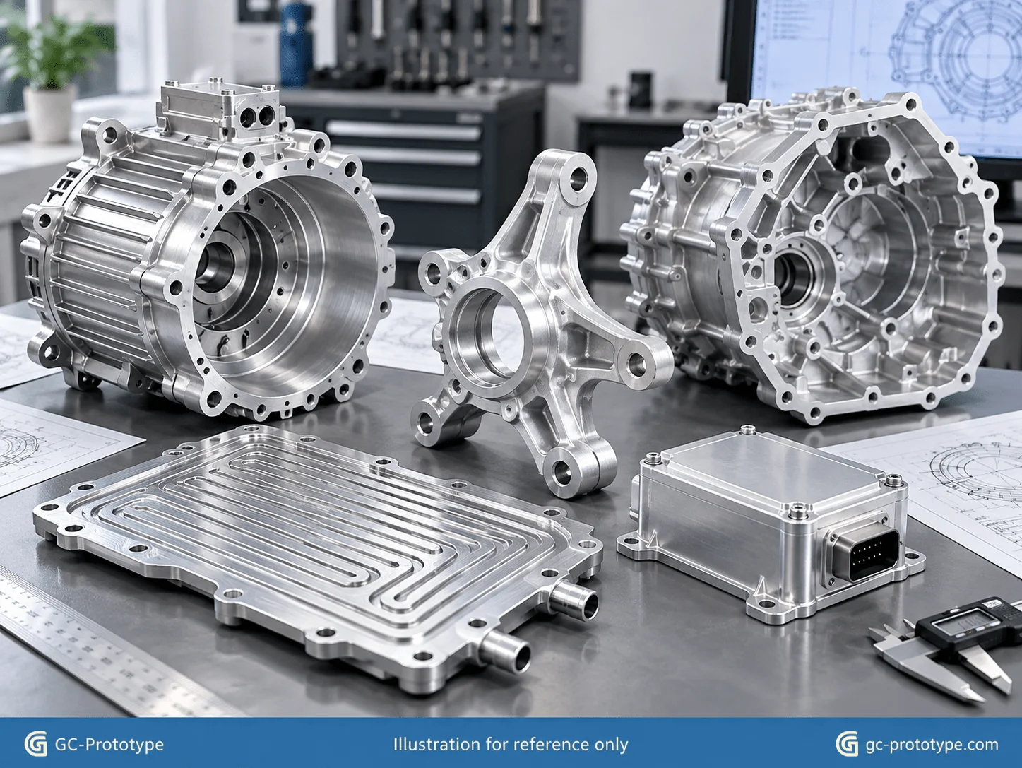
Typical precision-machined automotive components include:
Engine housings
Transmission components
Steering knuckles
Electric motor housings
Inverter enclosures
Battery cooling plates
Suspension brackets
Precision shafts
Bearing carriers
Sensor mounting components
Each component contains features with different functional requirements.
For example, an external housing surface may tolerate relatively broad dimensional variation, while a bearing seat or sealing interface may require substantially tighter control.
Poor tolerance control can produce several functional problems.
Bearing misalignment: Incorrect bore location or geometry can increase bearing load and reduce operating life.
Sealing leakage: Poor flatness or surface finish can prevent gaskets and O-rings from maintaining an effective seal.
Excessive vibration: Geometric variation in rotating assemblies may contribute to NVH problems.
Assembly interference: Incorrect hole positions or mating dimensions may prevent components from fitting together correctly.
Premature fatigue: Poor surface transitions, unexpected loading, and assembly misalignment can increase localized stresses.
However, specifying extreme precision on every feature is not an effective solution.
Over-tolerancing increases:
Machining time
Tool consumption
Inspection requirements
Scrap risk
Manufacturing costs
The engineering objective is to apply precision according to actual functional requirements.
During automotive development, engineers frequently need multiple prototype iterations.
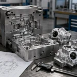
CNC machining provides the flexibility to manufacture functional metal components without investing in permanent casting dies or injection molds.
Design modifications can be introduced directly into updated CAD models.
This allows development teams to evaluate:
Mechanical fit
Structural stiffness
Thermal performance
Vibration behavior
Sealing performance
Assembly repeatability
before moving toward larger production quantities.
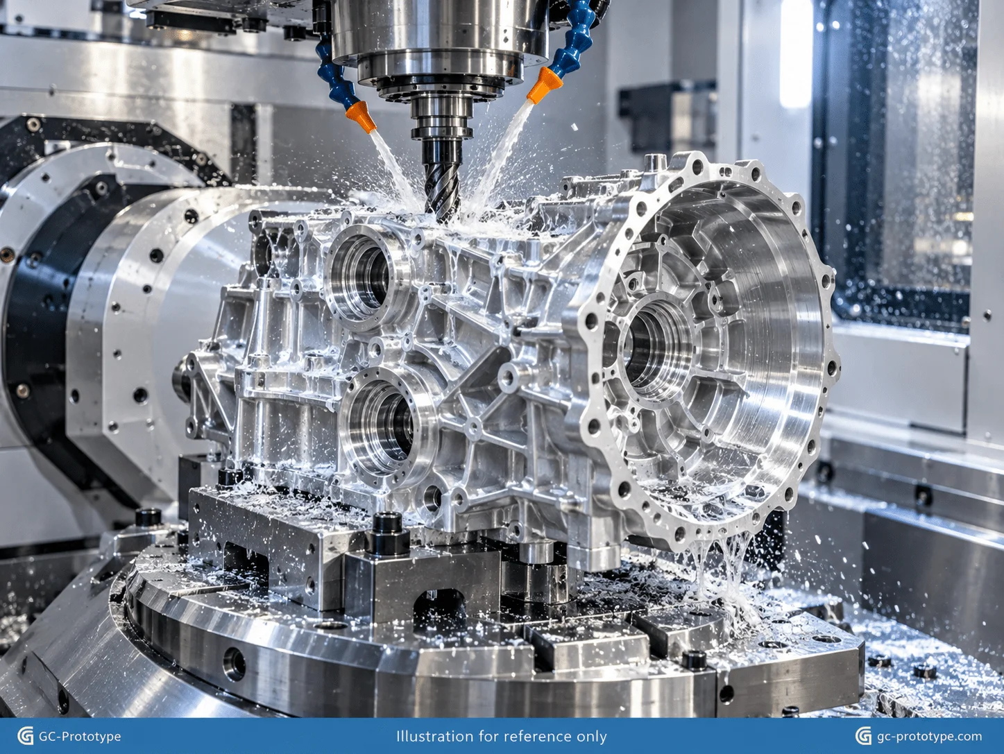
ISO 2768 tolerances for automotive cnc machining provide a useful framework for defining general manufacturing tolerances where individual dimensions do not require special controls.
ISO 2768-1 establishes general tolerance classes for certain linear and angular dimensions that are not individually toleranced.
Two commonly encountered classes are:
Fine (f)
Medium (m)
Fine tolerances allow less dimensional variation than medium tolerances for comparable nominal dimensions.
However, ISO 2768 should not be confused with an automotive regulatory certification or a universal precision guarantee.
Critical automotive features generally require explicit tolerances and GD&T rather than relying exclusively on general tolerance classes.
The following examples illustrate selected ISO 2768-1 linear dimensional tolerances.
| Nominal Dimension Range | Fine (f) | Medium (m) |
| Over 3–6 mm | ±0.05 mm | ±0.10 mm |
| Over 6–30 mm | ±0.10 mm | ±0.20 mm |
| Over 30–120 mm | ±0.15 mm | ±0.30 mm |
| Over 120–400 mm | ±0.20 mm | ±0.50 mm |
These examples apply to relevant linear dimensions under ISO 2768-1. Engineers should consult the applicable standard and drawing requirements, including separate provisions for angular and other dimensions.
For a noncritical exterior housing feature, medium tolerances may be sufficient.
However, a precision bearing interface may require an explicitly specified tolerance significantly tighter than the applicable general class.
Geometric Dimensioning and Tolerancing (GD&T) provides a more functional way to control automotive components.
Common geometric controls include:
Flatness
Perpendicularity
Position
Profile
Circular runout
Total runout
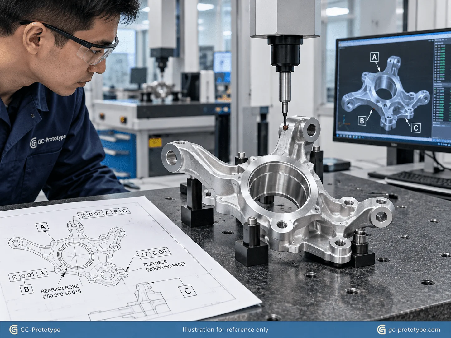
Consider a steering knuckle containing a bearing bore and multiple mounting holes.
The drawing may require precise control of:
1.Bearing bore diameter
2.Bearing bore position
3.Mounting face flatness
4.Hole-to-datum relationships
A flatness requirement below 0.01 mm may be appropriate for selected critical features, depending on geometry and performance requirements.
However, such values must be evaluated against manufacturing and measurement capability.
A datum reference establishes how a component is located and inspected.
Poor datum selection can create difficulties even when individual dimensions appear correct.
For example, an automotive housing may be machined using one reference surface but assembled using another.
If those surfaces do not have controlled geometric relationships, assembly variation can occur.
Automotive engineers should therefore select datums based on actual:
Assembly location
Load transfer
Bearing alignment
Sealing interfaces
This reduces ambiguity between design, machining, and inspection.
Aluminum cnc machining for electric vehicles has become increasingly important as EV manufacturers seek to reduce weight, improve thermal performance, and maintain precise mechanical alignment.
Electric vehicles contain many aluminum components, including:
Electric motor housings
Inverter enclosures
Battery cooling plates
Power electronics housings
Structural mounting brackets
Battery pack support structures
Aluminum provides several important engineering benefits:
Low density
Good thermal conductivity
Excellent CNC machinability
Corrosion resistance in suitable alloys and environments
Good strength-to-weight performance
Two commonly used engineering aluminum alloys are 6061-T6 and 6082-T6.
| Engineering Factor | 6061-T6 Aluminum | 6082-T6 Aluminum |
| Strength | Good | Generally higher |
| Machinability | Excellent | Good |
| Corrosion Resistance | Very good | Very good |
| Thermal Conductivity | Good | Good |
| CNC Prototype Applications | Housings, cooling components | Structural brackets, load-bearing parts |
| Material Availability | Common in North America | Common in European markets |
| Relative Cost | Application-dependent | Application-dependent |
Both alloys are suitable for many automotive prototypes.
The final choice depends on structural requirements, stock availability, thermal performance, and regional supply conditions.
Electric motor housings require accurate relationships between:
Bearing seats
Motor mounting interfaces
Cooling channels
Shaft centerlines
Housing covers
Poor alignment can contribute to vibration, abnormal bearing loads, and reduced mechanical efficiency.
Precision CNC machining can control these features during functional prototype manufacturing.
Electric powertrains generate heat in motors, inverters, and other high-power electronics.
Aluminum cold plates and cooling housings may incorporate:
Internal coolant channels
Heat-transfer surfaces
O-ring grooves
Threaded ports
Thin-wall structures
CNC machining allows engineers to test cooling geometry without waiting for high-volume manufacturing tooling.
Large aluminum pockets and thin walls can create machining challenges.
When substantial material is removed, residual stresses in the stock may be released.
The component can distort after unclamping.
Strategies for improving dimensional stability include:
Balanced rough machining
Controlled material removal
Appropriate fixturing
Intermediate stress relief where necessary
Finishing after dimensional stabilization
These practices are particularly valuable for large battery cooling components and thin-wall inverter housings.
Custom cnc machining for automotive prototypes allows automotive engineering teams to validate mechanical designs before investing in expensive production tooling.
During the development of a new vehicle or updated drivetrain, manufacturers may require functional prototype components for:
Dynamometer testing
Vehicle installation trials
Thermal cycling
Vibration testing
Mechanical durability testing
Assembly verification
These tests require components that accurately represent the intended mechanical design.
A plastic appearance model may be suitable for packaging evaluation but insufficient for testing a high-load aluminum or steel component.
CNC machining produces components directly from stock material.
This eliminates the requirement for dedicated casting dies during initial development.
A typical development sequence may involve:
CAD Design → CNC Prototype → Functional Testing → Design Revision → Updated Prototype
For relatively simple components using available materials, manufacturing may sometimes be completed within approximately 3–7 working days.
Actual lead time depends on:
Material availability
Part complexity
Machining capacity
Surface treatment
Inspection requirements
Complex parts may require longer.
Automotive prototype components should be manufactured from materials that provide meaningful engineering data.
For example, an aluminum motor housing prototype may be tested for:
Thermal expansion
Assembly alignment
Structural stiffness
Coolant sealing
Vibration resistance
Using a representative aluminum alloy allows engineering teams to evaluate performance more realistically than with an unrelated prototype plastic.
However, machined stock and a future cast part can have different material properties. If the final product will be die cast, validation must account for that difference.
CNC machining is valuable because it allows engineers to modify:
Wall thickness
Mounting geometry
Bearing interfaces
Cooling channels
Fastener locations
without rebuilding production tooling.
This flexibility is particularly important during early automotive development, when design changes are frequent.
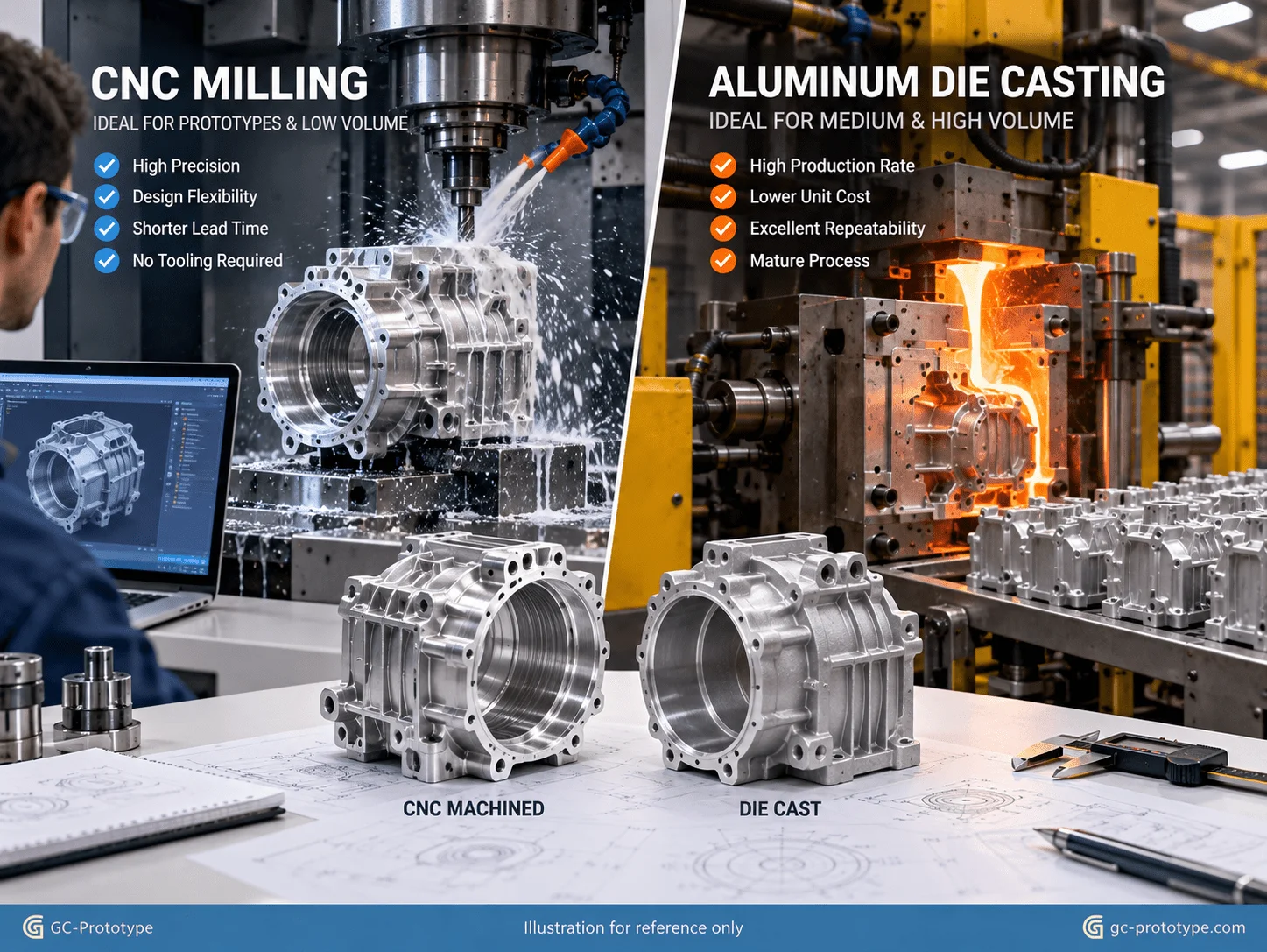
Evaluating cnc machining vs die casting for automotive parts is essential for procurement teams deciding how to transition from prototype development into pilot and mass production.
Both processes have important advantages.
CNC machining offers:
Minimal dedicated tooling investment
High design flexibility
Excellent precision
Fast engineering revisions
Die casting offers:
Efficient high-volume production
Complex near-net-shape geometry
Lower per-part manufacturing cost at sufficient volume
However, die casting generally requires a significant initial tooling investment.
| Evaluation Factor | CNC Machining | Die Casting |
| Initial Tooling Cost | Low | High |
| Prototype Flexibility | Excellent | Limited after tooling |
| Dimensional Precision | Excellent | Critical features often need CNC finishing |
| Low-Volume Production | Strong advantage | Depends on tooling economics |
| High-Volume Production | Higher unit machining cost | Often more economical |
| Design Changes | Relatively easy | May require tooling changes |
| Material Waste | Higher subtractive waste | Lower for near-net-shape geometry |
Consider a hypothetical aluminum housing project.
Assume:
CNC programming and setup: $350
CNC machining cost: $65 per component
Die-casting tooling: $18,000
Die-cast unit cost including required finishing: $17
| Production Quantity | CNC Machining Total | Die Casting Total |
| 10 parts | $1,000 | $18,170 |
| 100 parts | $6,850 | $19,700 |
| 500 parts | $32,850 | $26,500 |
| 2,000 parts | $130,350 | $52,000 |
Illustrative financial model only. These figures are not actual quotations or guaranteed market prices.
Under these assumptions, die casting becomes less expensive at approximately 368 parts.
However, the real crossover depends on geometry, alloy, tooling complexity, required secondary machining, surface treatment, scrap, and quality requirements.
For many engineering programs, CNC machining remains attractive during prototype and low-volume stages.
As volume increases, die casting may offer lower total manufacturing cost.
A practical approach is to use:
CNC Prototype → Functional Validation → Pilot Production → Die Casting + CNC Finishing
This allows engineers to validate geometry before committing to casting tools.
It also preserves precision on critical bearing seats, sealing interfaces, and mounting surfaces after die casting.
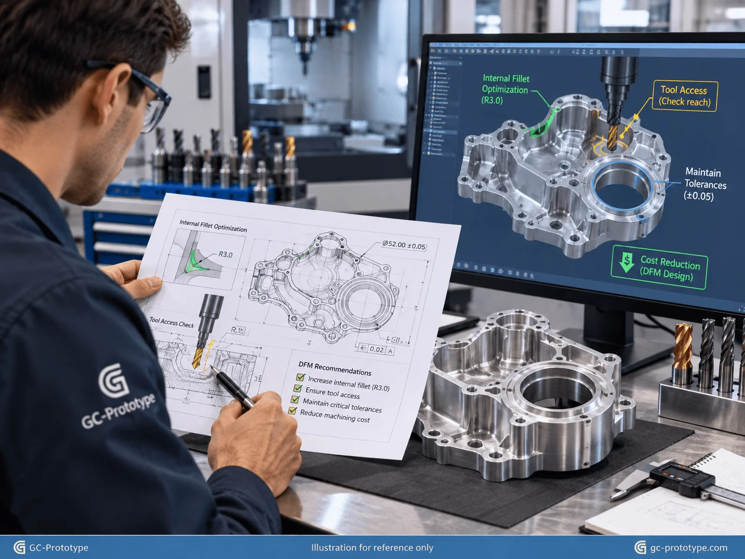
Design for Manufacturability (DFM) is one of the most effective ways to reduce automotive CNC machining costs.
A component may be technically manufacturable but unnecessarily expensive because of avoidable design features.
Common problems include:
Excessively tight tolerances
Deep internal pockets
Small internal corner radii
Thin unsupported walls
Unnecessary surface finishing
Machining costs typically increase as tolerances become more demanding.
Consider two dimensions:
±0.05 mm
±0.005 mm
The second tolerance is ten times tighter.
However, the manufacturing cost does not necessarily increase by exactly ten times.
Cost depends on the selected process and how close the requirement is to the machine’s practical capability.
| Tolerance Level | Relative Difficulty | Typical Application |
| ±0.10 mm | Low | Noncritical geometry |
| ±0.05 mm | Moderate | General assembly |
| ±0.01 mm | High | Precision mounting interfaces |
| ±0.005 mm | Very High | Selected critical features |
Illustrative tolerance categories; actual difficulty depends on material, feature size, machine capability, and inspection.
When very tight tolerances are specified, manufacturers may need:
Additional finishing passes
Slower cutting parameters
Specialized measurement equipment
Temperature-controlled inspection
More frequent quality checks
Therefore, unnecessary micrometer-level tolerances can increase cost significantly.
Engineers should identify the features that directly influence:
Assembly alignment
Bearing performance
Sealing
Functional movement
These features may require tight dimensional or geometric controls.
Noncritical exterior surfaces can often use more economical general tolerances.
This allows suppliers to maintain functional precision without wasting machining time.
Very small internal radii require small cutting tools.
Small tools may:
Increase machining time
Deflect more easily
Wear faster
Where functional requirements permit, larger internal corner radii allow more efficient material removal.
Automotive aluminum parts frequently require surface finishing for corrosion resistance, wear resistance, or electrical functionality.
Common options include:
Hard anodizing: Useful for improving surface hardness and wear resistance in suitable applications.
Chromate conversion coating: May provide corrosion protection while maintaining electrical conductivity where specified.
These treatments are not interchangeable.
Anodized surfaces are generally electrically insulating, so electrical grounding interfaces may require masking or specific contact features.
Finishing requirements should be established during DFM because coating thickness and electrical characteristics can affect component performance.
Substantial savings may be possible when an original design contains significant manufacturing inefficiencies.
Examples include:
Reducing unnecessary tight tolerances
Improving machining access
Lowering material waste
Eliminating redundant setups
Avoiding unnecessary finishing
A cost reduction of 25% or more may be achievable in some redesign projects, but it should not be presented as a universal guarantee.
An EV engineering team develops an aluminum motor housing requiring:
Accurate bearing bores
Precision mounting datums
Cooling interfaces
Controlled concentric relationships
CNC machining supports functional validation before production tooling.
A chassis engineering team requires a steering knuckle for mechanical testing.
Critical characteristics include:
Bearing bore geometry
Mounting hole position
Structural integrity
Assembly alignment
Five-axis machining may reduce setups and improve access to complex geometry.
A battery thermal-management team needs a prototype with:
Internal coolant channels
Sealing grooves
Flat mating surfaces
Threaded connections
CNC machining allows the cooling design to be tested before investing in production tooling.
A transmission prototype may require:
Accurate shaft alignment
Bearing support
Sealing interfaces
Rigid mounting surfaces
Precision machining supports assembly and durability testing.
Advanced driver-assistance systems use sensors requiring mechanically stable mounting.
CNC aluminum housings can provide:
Accurate locating datums
Thermal management
Robust threaded interfaces
Suitable electrical grounding features
Automotive component development should connect early engineering decisions with future production requirements.
GC Prototype supports customers through the complete manufacturing development process.
Engineering teams define:
Material specifications
Critical dimensions
GD&T
Surface treatments
Inspection requirements
A DFM review identifies manufacturing risks and unnecessary costs before machining begins.
Initial CNC-machined components allow engineers to evaluate:
Mechanical fit
Assembly
Structural stiffness
Thermal performance
Production-intent prototypes may undergo:
Vibration testing
Thermal cycling
Durability testing
Fluid sealing tests
Assembly verification
Pilot quantities help evaluate:
Manufacturing consistency
Inspection procedures
Cost stability
Assembly workflow
Once the design is stable, manufacturing strategy can be optimized according to:
Production volume
Unit-cost targets
Material requirements
Quality expectations
Depending on the component, production may continue with CNC machining or transition to die casting, extrusion, or other scalable manufacturing processes.
General machining tolerances may range from approximately ±0.10 mm to ±0.05 mm for many features, while critical bearing, sealing, and locating interfaces may require tighter requirements.
Actual specifications depend on component geometry and function.
ISO 2768-1 defines general tolerances for certain linear and angular dimensions. It helps standardize drawing requirements for dimensions without individual tolerance specifications.
Critical automotive features should use explicit dimensions and GD&T where necessary.
Selected features may achieve approximately ±0.005 mm under appropriate conditions, but capability depends on material, machine accuracy, geometry, fixturing, thermal stability, and inspection.
Yes. 6061 aluminum is commonly suitable for machined EV housings, cooling components, brackets, and structural prototypes when its properties meet the design requirements.
CNC machining allows engineers to manufacture functional metal components without dedicated production tooling, supporting faster design revisions and mechanical testing.
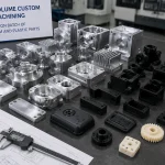
For low quantities, CNC machining often avoids the high initial tooling costs of die casting.
At higher production volumes, die casting may become more economical depending on component geometry and manufacturing requirements.
Use realistic tolerances, improve tool accessibility, optimize internal radii, reduce redundant setups, and select surface treatments according to function.
Five-axis machining improves access to complex geometries and may reduce re-clamping operations, helping maintain relationships between critical surfaces and features.
A complete RFQ should include:
3D CAD/STEP model
2D engineering drawing
Material grade
Quantity
Critical tolerances and GD&T
Surface treatment
Inspection requirements
Testing or documentation expectations
GC Prototype supports the complete development process from CAD and prototype samples through functional validation, low-volume pilot production, and mass production support.
Automotive precision machining is not simply about manufacturing every feature to the tightest possible tolerance.
The objective is to control the dimensions that directly influence:
Mechanical assembly
Dynamic performance
Bearing alignment
Sealing reliability
Thermal efficiency
Component durability
Applying iso 2768 tolerances for automotive cnc machining appropriately helps engineering teams establish consistent general dimensional requirements while using GD&T for critical functional interfaces.
For EV development, aluminum cnc machining for electric vehicles supports lightweight structures, thermal-management components, and accurate mechanical assemblies.
During NPI, custom cnc machining for automotive prototypes provides the flexibility to validate engineering designs before committing to expensive production tooling.
Procurement teams evaluating cnc machining vs die casting for automotive parts should consider total manufacturing cost, production quantity, design flexibility, and future tooling requirements rather than comparing unit prices alone.
By combining intelligent tolerance selection, appropriate materials, CNC process optimization, and early DFM review, automotive manufacturers can improve prototype reliability while controlling development budgets.
GC Prototype supports automotive and EV engineering teams through the complete manufacturing development journey:
CAD → Prototype Samples → Functional Validation → Low-Volume Pilot Production → Mass Production Support
Achieving micrometer-level precision for high-load automotive assemblies shouldn’t delay your NPI launch or exhaust your prototyping budget. Whether you are an Automotive Design Engineer finalizing tight-tolerance EV inverter housings or a Sourcing Manager evaluating CNC machining versus die casting, GC Prototype provides precision engineering and manufacturing support.