Address:
Shenzhen Bao'an District Xinqiao Subdistrict Huangpu Community Huangpu East Ring Road No. 504 Shenzhen Yuan Industrial City Building C
Work Hours:
Monday to Friday: 9AM - 21PM
Weekend: 9AM - 21PM

Address:
Shenzhen Bao'an District Xinqiao Subdistrict Huangpu Community Huangpu East Ring Road No. 504 Shenzhen Yuan Industrial City Building C
Work Hours:
Monday to Friday: 9AM - 21PM
Weekend: 9AM - 21PM

Rapid CNC Prototyping has become a critical engineering route for robotics teams that need to validate high-load structures, precision joints, and real mechanical behavior before committing to a final design. When evaluating rapid cnc prototyping vs 3d printing for robotics, engineers often find that printed polymer parts are excellent for early geometry checks but may not provide the rigidity, wear resistance, thermal behavior, or dimensional stability required for dynamic testing. CNC machining fills this gap by producing functional prototypes directly from engineering-grade aluminum, stainless steel, titanium, and plastics.
For Robotics Engineers, Senior Mechanical Engineers, NPI Engineers, and Sourcing Managers, successful robot development depends on more than simply manufacturing a CAD model. Material stiffness, weight, joint tolerances, bearing alignment, machining accessibility, surface treatment, and prototype lead time all influence whether a robotic system performs as expected during real testing.
This guide explains how rapid CNC prototyping helps robotics teams validate structural integrity, reduce inertia, control critical joint interfaces, compare machining with additive manufacturing, and optimize prototype costs through practical DFM.
Why Rapid CNC Prototyping Matters in Robotics NPI
Robotic hardware experiences mechanical conditions that are difficult to reproduce with appearance-only prototypes. Robot arms, actuator housings, end effectors, sensor brackets, mobile platforms, and joint structures may experience continuous vibration, impact, repeated acceleration, thermal cycles, and high torque.
During NPI, engineers often need prototypes for:
Static load testing
Dynamic motion verification
Servo tuning
Bearing alignment
Gearbox integration
Thermal testing
Drop or impact evaluation
Cable-routing validation
Sensor positioning
Assembly verification
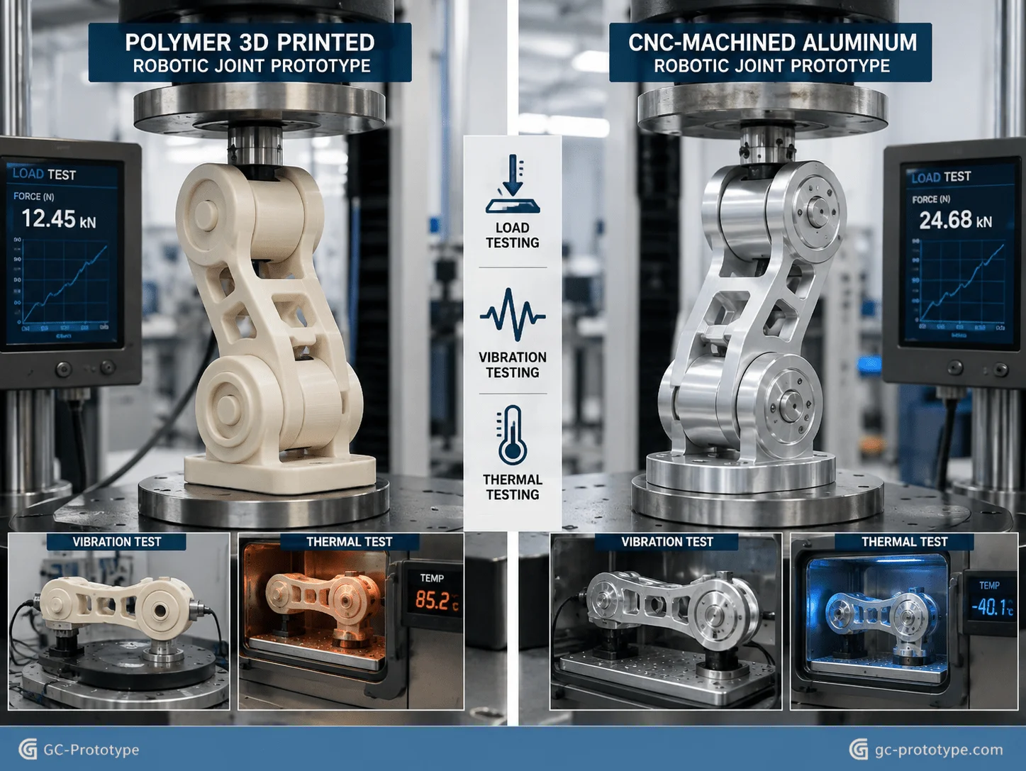
A polymer 3D print may demonstrate shape and packaging successfully, but its stiffness may be dramatically different from an aluminum prototype. If the mechanical properties differ too much from the intended structure, the prototype may produce misleading results during vibration, positioning, or thermal testing.
Rapid CNC machining addresses this issue by using real engineering materials without requiring dedicated molds or dies.
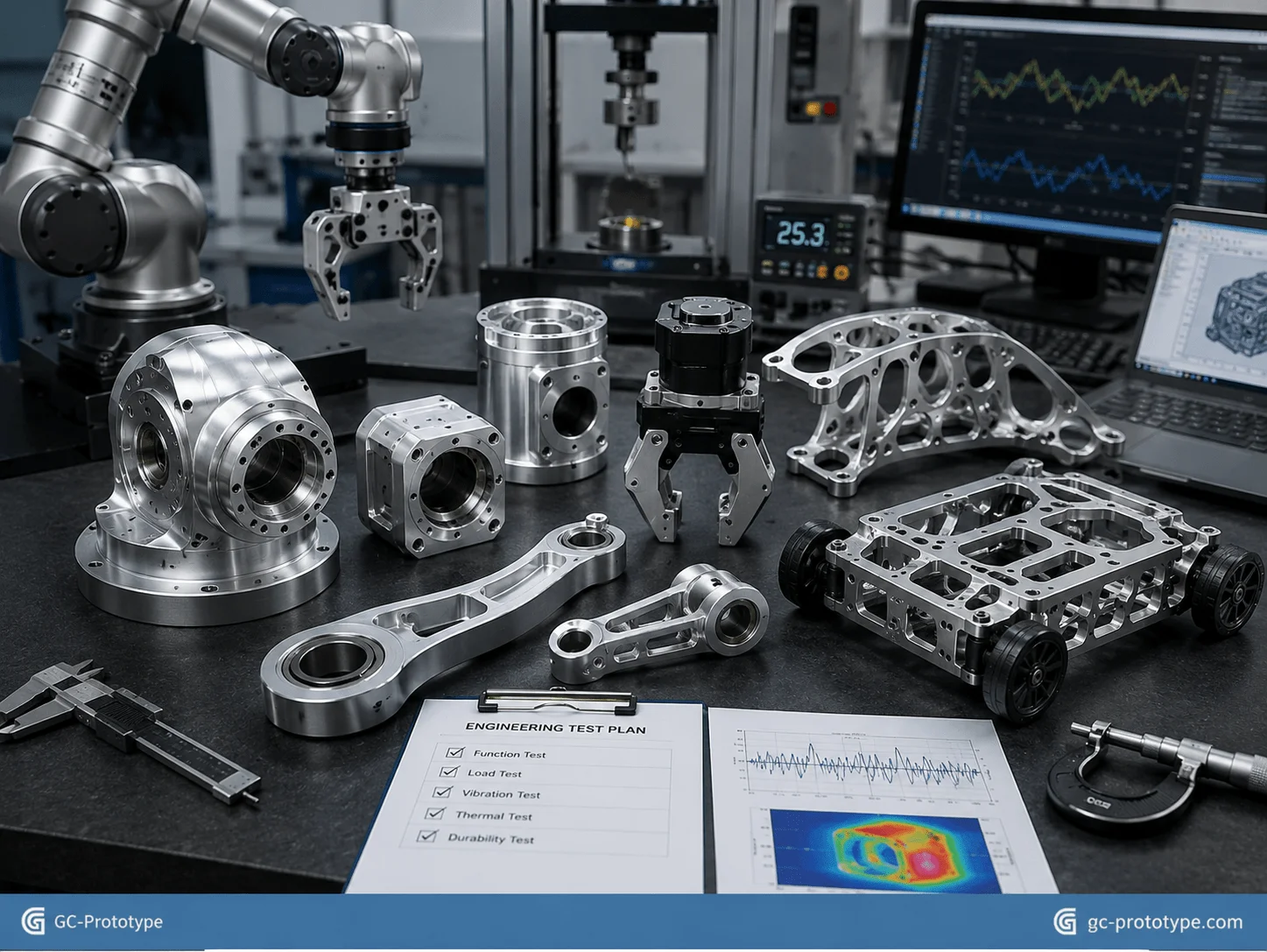
A typical robotics prototype workflow may include:
1.CAD design and tolerance definition
2.Engineering DFM review
3.Material selection
4.CNC milling or turning
5.Deburring and dimensional inspection
6.Anodizing or other required finish
7.Mechanical assembly
8.Dynamic functional testing
9.CAD revision based on test results
Because prototype tooling is minimal, engineering changes can be implemented rapidly. This is particularly valuable when a robot requires several mechanical iterations before the joint geometry, motor selection, or structural stiffness is finalized.
For GC Prototype, the focus is prototype manufacturing and engineering validation rather than mass-production supply. The objective is to help engineering teams obtain reliable physical test parts quickly enough to make better design decisions before moving to their later manufacturing stage.
Industry Applications & Material Selection
Structural Integrity: Selecting lightweight aluminum alloys for robotics cnc machining
Selecting lightweight aluminum alloys for robotics cnc machining requires balancing stiffness, strength, weight, machinability, thermal performance, surface treatment, and prototype budget.
Weight is particularly important in robotics because every additional gram located far from a joint axis contributes to rotational inertia. A heavier end effector can require higher motor torque, increase energy consumption, slow acceleration, and make servo tuning more difficult.
For this reason, robotics engineers frequently use aluminum for:
Robot arm links
Joint housings
Motor brackets
Sensor frames
End-effector bodies
Mobile-robot chassis components
Camera mounts
Electronics enclosures
Two commonly evaluated aluminum grades are 6061-T6 and 7075-T6.
| Property | 6061-T6 | 7075-T6 | Design Implication |
|---|---|---|---|
| Strength | Good | Significantly higher | 7075 suits highly loaded structures |
| Machinability | Excellent | Excellent | Both are CNC-friendly |
| Corrosion Resistance | Very good | Lower than 6061 | 6061 often suits general housings |
| Anodizing | Widely used | Possible, appearance may differ | Verify cosmetic requirements |
| Cost | Lower | Higher | 6061 is economical for many prototypes |
| Typical Robotics Use | Housings, brackets, frames | Highly loaded joints and lightweight structures | Select by load case |
6061-T6 is often an excellent starting point for functional prototypes because it provides good stiffness, machining performance, corrosion resistance, and cost efficiency. It is particularly suitable for electronic enclosures, sensor brackets, chassis structures, and general-purpose arm components.
7075-T6 offers considerably higher strength and may allow engineers to reduce material in highly loaded structures. This can be valuable for robot joints, lightweight arm links, and other components where strength-to-weight ratio matters more than material price.
Magnesium-based alloys may offer further weight reduction in specialized designs, but material availability, corrosion protection, machining practices, and project requirements should be evaluated carefully before selection.
Material choice should always follow the test objective. If an R&D team is validating servo response and structural deflection, selecting a prototype material with stiffness close to the intended mechanical design is far more informative than using a low-stiffness visual prototype.
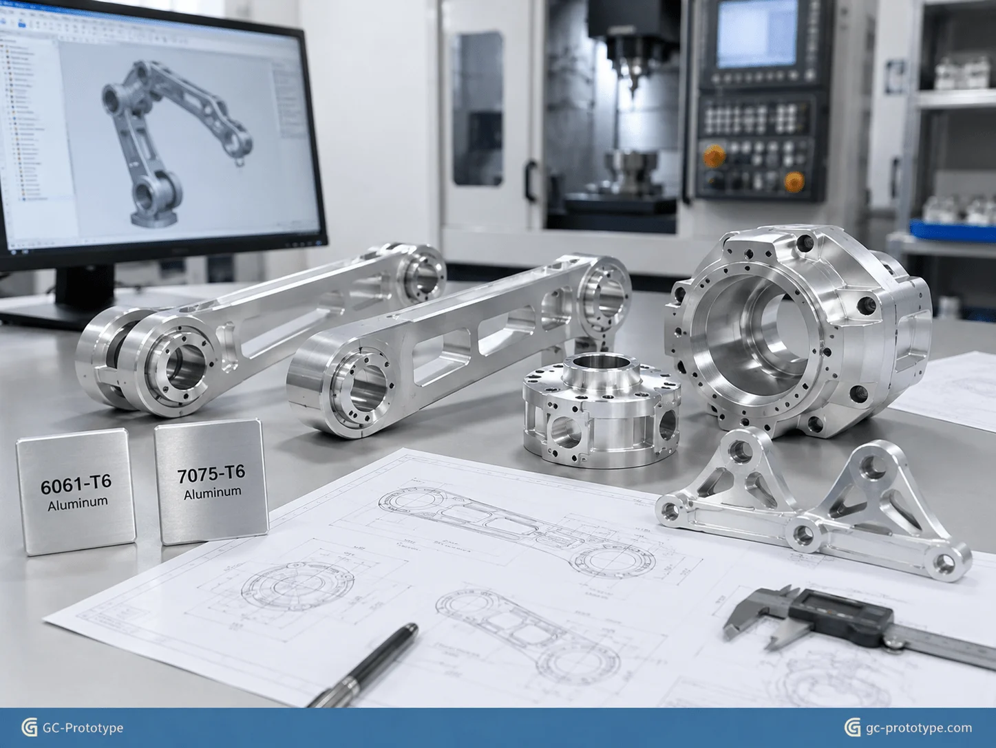
Custom End-Effectors & Chassis: Sourcing custom cnc machined robotics parts
Sourcing custom cnc machined robotics parts gives Hardware Engineers and Product Designers the flexibility to test specialized mechanical structures without designing around the limitations of standard off-the-shelf components.
Robotics development often requires highly customized parts because every system has different payloads, sensors, actuators, workspace limitations, and mechanical interfaces.
Typical custom prototypes include:
Collaborative robot grippers
End-effector plates
Camera mounts
LiDAR brackets
Sensor protection housings
Motor mounts
Mobile robot chassis brackets
Suspension components
Gearbox housings
Cable-management components
Multi-axis CNC machining is especially useful when a prototype combines complex surfaces, deep pockets, mounting interfaces, and multiple hole orientations.
A traditional machining strategy may require several setups. Each time the prototype is unclamped and repositioned, additional setup time and potential alignment error are introduced.
With 4-axis or 5-axis machining, more features can often be completed in fewer setups. This can improve both lead time and the positional relationship between critical interfaces.
Thin-wall machining is another important robotics application.
A lightweight robot housing may require:
Internal material removal
Thin external walls
Reinforcement ribs
Precision bearing seats
Cable passages
Threaded mounting locations
Although aggressive material removal reduces weight, excessively thin structures can distort during machining or vibrate during robot operation.
The DFM objective is therefore not to remove the maximum possible amount of metal. It is to remove material strategically while preserving stiffness around load paths, bearing interfaces, and mounting locations.
Prototype machining also allows engineers to test real fastening methods. Threaded inserts, tapped aluminum holes, dowel locations, precision shoulders, and bearing bores can be evaluated during physical assembly rather than simulated only in CAD.
This is a major advantage during robotics NPI because assembly behavior often reveals issues that are difficult to predict digitally.
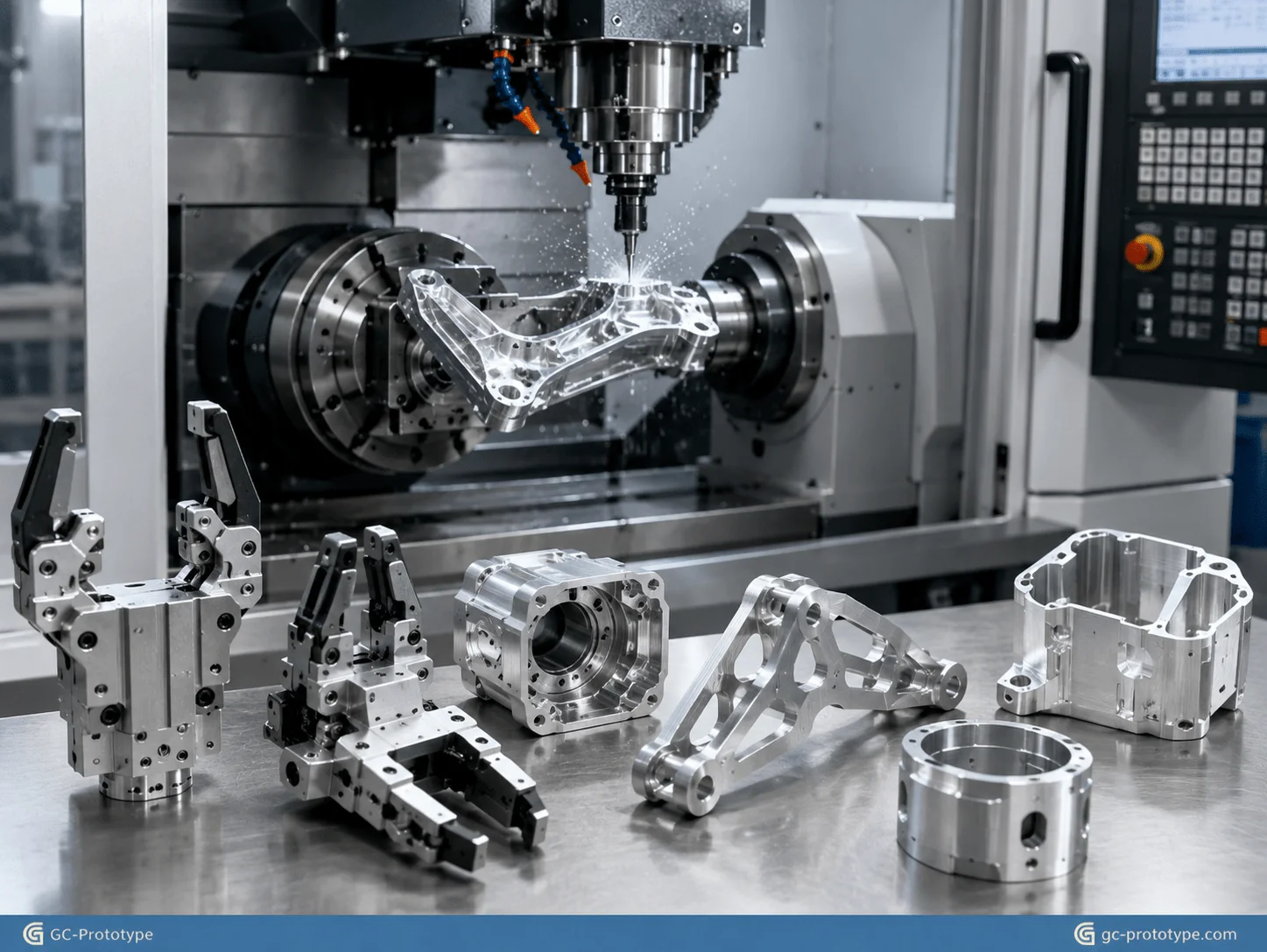
Engineering Precision & Process Trade-Offs
High-Precision Assembly: Controlling cnc machining tolerances for robot arm joints
Controlling cnc machining tolerances for robot arm joints is essential when prototypes must reproduce realistic mechanical alignment, backlash, runout, and positioning behavior.
Robot joints often combine:
Harmonic reducers
Servo motors
Bearings
Output flanges
Encoders
Seals
Fasteners
These components interact through precisely machined interfaces.
A small misalignment between the gearbox and motor may increase vibration or bearing load. An inaccurate bearing seat can create unwanted clearance. Poor perpendicularity between a flange and rotational axis can produce runout at the end effector.
Critical specifications may therefore include:
Coaxiality
Perpendicularity
Flatness
Parallelism
Bore diameter
Shaft fit
Bearing fit
Hole position
Surface roughness
The article outline references ISO 2768-f and tolerances down to approximately ±0.01 mm. These should not be treated as interchangeable requirements: ISO 2768 general tolerances vary according to feature size and tolerance class, while ±0.01 mm is typically a separately specified tight feature tolerance. Engineers should identify exactly which joint features need this level of control rather than assigning it to the entire component.
For example, a robot joint housing may have:
| Feature | Typical Engineering Priority |
|---|---|
| Bearing bore | Very high |
| Gearbox locating diameter | Very high |
| Motor mounting face | High |
| Encoder mounting interface | High |
| Cable opening | Moderate |
| External cosmetic wall | General tolerance |
If ±0.01 mm is applied to every surface, machining and inspection time can increase dramatically without improving robot performance.
A better approach is creating a functional tolerance hierarchy.
The most critical interfaces receive tight dimensional or geometric controls. Nonfunctional geometry receives practical general tolerances.
Why Datum Strategy Matters
Robotic joint accuracy is not determined by individual dimensions alone.
The relationship between features is often more important.
Suppose a bearing bore is machined accurately, but the motor flange is not perpendicular to its rotational axis. The components may each pass individual diameter inspection while the assembled joint still performs poorly.
Engineering drawings should therefore establish functional datums that represent how the joint actually assembles.
A supplier can then plan machining and inspection around those datums.
Reducing setups also helps. Machining critical coaxial features without re-clamping the workpiece can reduce accumulated setup variation.
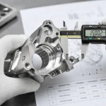
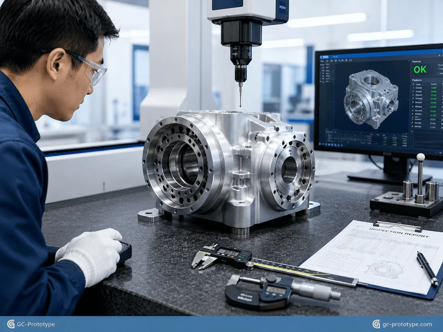
For high-precision robotics prototypes, inspection may involve:
CMM measurement
Bore gauges
Micrometers
Height gauges
Surface roughness measurement
Functional assembly checks
Inspection scope should match the prototype purpose. A high-load dynamic joint prototype deserves more rigorous measurement than an early enclosure mock-up.
Functional Verification: rapid cnc prototyping vs 3d printing for robotics
Comparing rapid cnc prototyping vs 3d printing for robotics requires separating visual validation from mechanical validation.
Both technologies are valuable, but they answer different engineering questions.
| Evaluation Factor | CNC Prototype | 3D Printed Prototype |
|---|---|---|
| CAD Geometry Check | Excellent | Excellent |
| Fast Early Iteration | Good | Excellent |
| Real Aluminum Properties | Excellent | Not with polymer printing |
| Tight Bearing Interfaces | Excellent | Usually requires secondary work |
| High-Torque Testing | Excellent | Material-dependent |
| Complex Internal Geometry | Limited by tooling | Excellent |
| Lightweight Lattice Structures | Difficult | Excellent |
| Threaded Metal Interfaces | Excellent | Limited for polymer prints |
| Drop/Impact Test Realism | High with intended material | Material-dependent |
| Cost for Simple Visual Model | Higher | Usually lower |
For one early ergonomic model, 3D printing is often the logical choice.
But imagine a robotic end effector that must carry a 10 kg payload while accelerating repeatedly. A polymer print may confirm mounting locations and cable routing but may flex far more than the final metal structure.
If engineers use that prototype for servo tuning or structural evaluation, test results may not represent the final design.
A machined aluminum prototype gives the team far more realistic information about:
Deflection
Vibration
Fastener behavior
Thread performance
Heat transfer
Bearing support
Structural resonance
Impact resistance
Prototype Cost Analysis
For a 1–10 set robotics prototype program, cost should be evaluated according to what needs to be learned.
3D printing may have a lower purchase price for highly complex plastic geometry. CNC machining may cost more per component, but it can prevent expensive engineering mistakes when the objective is structural validation.
Typical CNC prototype cost drivers include:
Raw material
Number of setups
Machine time
Tool access
Tolerances
Inspection
Surface treatment
Quantity
Typical 3D printing cost drivers include:
Build volume
Material
Support requirements
Printing process
Post-processing
Surface finish
The lowest quoted part price is therefore not always the lowest engineering cost.
If a $100 visual prototype cannot answer a critical load question, while a $300 metal prototype prevents a major joint redesign later, the more expensive component may provide significantly better R&D value.
This is especially relevant to robotics, where small mechanical errors can propagate through an entire kinematic chain.
DFM Optimization & Fast Turnaround Sourcing
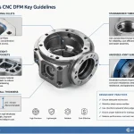
DFM Best Practices for Robotics: Reducing Lead Times and Machining Costs
Effective DFM can reduce CNC prototype cost without sacrificing the mechanical performance needed for robotics testing.
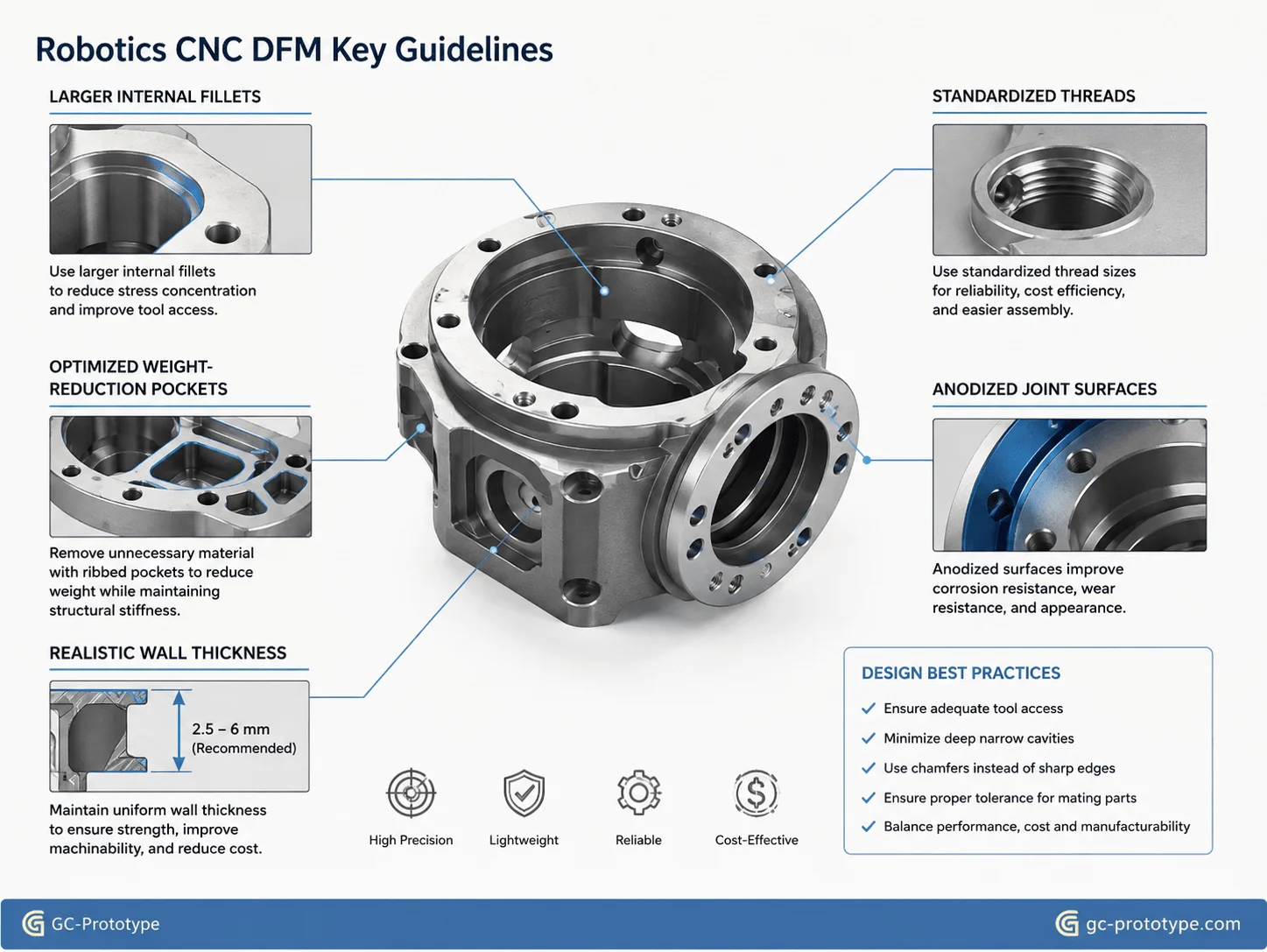
Increase Internal Corner Radii
A rotating end mill naturally creates radiused internal corners.
Very small fillets require small cutting tools, and small tools remove material more slowly. They may also need reduced cutting depth to avoid breakage.
If a pocket does not require a tiny internal radius, increasing the fillet allows the machinist to use a larger, more rigid cutter.
This can reduce:
Machining time
Tool changes
Vibration
Tool wear
Deep cavities benefit especially from larger radii.
Optimize Weight-Reduction Pockets
Lightweighting is important, but excessively thin walls can increase cost and reduce prototype reliability.
When a deep pocket leaves a thin wall, machining stresses can cause the component to distort after material is removed.
For robot arm components, the better approach is maintaining material around:
Joint interfaces
Bearing seats
Fastener locations
High-load paths
while removing material from lower-stress regions.
Topology optimization or FEA can help identify these areas, but final geometry should still be reviewed for machinability.
Avoid Unnecessarily Deep Cavities
Deep pockets require long tools. Long tools are less rigid and more likely to vibrate.
If a deep pocket exists only to reduce weight, engineers should evaluate whether a shallower pocket or alternative geometry provides nearly the same mass reduction with much lower machining time.
Standardize Holes and Threads
Robotics prototypes often contain many fasteners.
Using standard:
Thread sizes
Counterbores
Countersinks
Reamed holes
helps reduce special tooling and simplifies assembly.
Thread depth should also be practical. Extremely deep threads rarely provide proportional mechanical benefit and may increase tool-breakage risk.
Design Critical Interfaces for One Setup
Bearing bores, gearbox pilots, and motor interfaces should be arranged so critical relationships can be machined without unnecessary repositioning when possible.
This improves both cost and geometric consistency.
Use Anodizing Strategically
Aluminum robotics prototypes frequently use anodizing to improve appearance and surface protection.
Type II anodizing is common for general corrosion protection and cosmetic finishes. Type III hard anodizing may be selected when increased surface hardness and wear resistance are important.
Typical prototype applications include:
Joint housings
Grippers
Robot arm links
Chassis components
Sensor brackets
However, anodizing adds surface thickness and can affect precision fits. Tight bearing seats, grounding points, or critical threaded features may require masking or tolerance compensation.
The finish should therefore be included in the drawing before machining rather than added as an afterthought.
| DFM Issue | Cost/Quality Risk | Better Approach |
|---|---|---|
| Tiny internal fillets | Slow machining | Increase radius |
| Extremely deep pockets | Long tool reach | Reduce depth where possible |
| Thin unsupported walls | Distortion | Keep stiffness around load paths |
| Tight tolerance everywhere | High machining/inspection cost | Apply only to functional interfaces |
| Custom fasteners | Tooling complexity | Use standard threads |
| Finish added after design | Fit problems | Account for coating early |
Prototype Procurement Strategy for Robotics Teams
Prototype sourcing should support engineering learning rather than simply minimize the purchase order value.
For a robotics NPI program, Procurement Managers may need to source:
One initial mechanical concept
Three revised joint housings
Five end-effector variants
Ten complete functional prototype sets
Because the design can change after every test cycle, flexibility is more valuable than committing to volume.
Rapid CNC prototyping allows the sourcing team to purchase only what engineering currently needs.
This reduces:
Obsolete prototype inventory
Sunk tooling cost
Design-change penalties
Waiting time between iterations
Match Prototype Quantity to Test Objectives
Instead of ordering 50 components because the unit price appears lower, determine how many parts each validation stage actually requires.
For example:
EVT-style mechanical verification:
2–5 sets may be enough to verify interfaces, loading, and assembly.
Dynamic durability testing:
Additional sets may be required for repeated cycling or destructive tests.
Customer demonstration prototypes:
Several cosmetically finished units may be needed after the mechanical design is stable.
This staged sourcing strategy keeps capital aligned with engineering progress.
What to Include in a CNC Prototype RFQ
A complete RFQ should include:
STEP or other suitable 3D CAD files
2D technical drawings
Material
Quantity
Critical tolerances
Geometric tolerances
Threads
Surface roughness
Anodizing or other finish
Inspection requirements
Required delivery target
The supplier should also understand what the prototype is intended to test.
If the part is used for high-load joint testing, critical features may deserve additional inspection. If it is only an enclosure prototype, the quality plan can be simpler.
Clear communication prevents both under-processing and unnecessary cost.
Robotics Prototype Application Scenarios
High-Torque Robot Joint Housing
A robotics team needs three aluminum housings to test a new harmonic-drive joint. The prototype includes precision bearing bores, a motor locating flange, encoder mounting features, and internal weight-reduction pockets.
CNC machining provides realistic stiffness and allows the team to evaluate vibration and positioning behavior.
Collaborative Robot Gripper
A Product Designer develops several gripper geometries for a cobot.
Early shapes are tested using 3D printing. Once finger geometry and packaging are finalized, the team orders aluminum CNC prototypes for payload, impact, and repeated-cycle testing.
Mobile Robot Sensor Protection Housing
An autonomous mobile robot needs a lightweight protective enclosure around LiDAR and camera hardware.
A CNC-machined aluminum prototype allows engineers to test mounting rigidity, heat dissipation, impact protection, and sensor alignment.
Lightweight Robotic Arm Link
An R&D Engineer needs to reduce moving mass without reducing joint stiffness.
The prototype uses 7075-T6 aluminum with strategically machined pockets. Physical testing measures deflection and servo response before the design is finalized.
Robotic Chassis Suspension Bracket
A mobile robotics team develops a custom suspension bracket subjected to repeated vibration and shock loading.
A machined aluminum prototype provides much more representative mechanical behavior than a visual polymer model, allowing real fasteners and bearings to be evaluated.
Frequently Asked Questions About Rapid CNC Prototyping for Robotics
Why Is CNC Machining Useful for Robotics Prototypes?
CNC machining produces prototypes from real engineering metals and plastics, allowing teams to evaluate stiffness, threads, bearing interfaces, vibration, heat transfer, and other physical behavior more realistically than many visual prototype methods.
When Should Robotics Engineers Use 3D Printing Instead?
3D printing is excellent for early geometry validation, ergonomic studies, complex internal shapes, lightweight concept structures, cable-routing checks, and rapid design iterations where final material properties are not yet required.
When Should a Robotics Prototype Switch From 3D Printing to CNC?
CNC machining becomes especially valuable once engineers need realistic structural testing, high torque, precise bearing fits, metal threads, real thermal behavior, or tight dimensional interfaces.
Is 6061-T6 or 7075-T6 Better for Robot Parts?
6061-T6 is cost-effective, corrosion resistant, and highly machinable, making it suitable for many general robotics prototypes. 7075-T6 offers higher strength and is attractive for highly loaded lightweight structures. The correct choice depends on the load case and test objective.
Can CNC Machining Achieve ±0.01 mm Tolerances?
Selected features can often be machined to approximately ±0.01 mm under appropriate conditions, but capability depends on geometry, material, feature size, machine setup, temperature, and inspection method. Such tight tolerances should be specified only where function requires them.
Why Are Tight Robot Joint Tolerances Important?
Bearing seats, gearbox locating diameters, motor flanges, and rotational interfaces influence runout, alignment, vibration, and positioning. Small errors can accumulate through the robotic kinematic chain.
How Can I Reduce the Cost of a Robotics CNC Prototype?
Increase internal corner radii, reduce unnecessarily deep pockets, use standard threads, apply tight tolerances selectively, simplify setups, and avoid removing material purely for cosmetic reasons.
Does Anodizing Affect CNC Tolerances?
Yes. Anodizing adds a surface layer and can influence close fits. Critical bearing interfaces, threads, and electrical contact areas may require masking or dimensional compensation.
What Quantity Is Suitable for Rapid CNC Prototyping?
Rapid CNC machining is especially useful for one-off parts and small prototype batches such as 1–10 sets, although the appropriate quantity depends on the engineering validation plan.
Does GC Prototype Supply Mass-Production Robotics Parts?
GC Prototype focuses on prototype manufacturing and engineering validation parts, helping robotics teams move from CAD concepts to functional physical testing. The service is intended for rapid prototyping rather than mass-production supply.
What Files Should I Send for a Robotics CNC Quote?
Provide your STEP/CAD model, 2D drawings where critical specifications are required, material, quantity, tolerances, surface finish, threads, anodizing requirements, and any inspection expectations.
Accelerate Robotics Engineering With Functional CNC Prototypes
Robotics development depends on rapid learning. CAD simulation can predict behavior, and 3D printing can validate geometry quickly, but high-load mechanical systems ultimately need physical prototypes that reproduce realistic stiffness, interfaces, threads, bearing fits, and thermal behavior.
Rapid CNC prototyping provides that bridge.
By machining functional components from 6061-T6, 7075-T6, stainless steel, titanium, or suitable engineering plastics, robotics teams can validate joint performance, end-effector strength, sensor alignment, structural vibration, and assembly accuracy before finalizing the design.
The most effective prototype strategy is not to specify maximum precision everywhere. It is to identify the features that control robot performance and apply engineering resources where they matter most.
Large internal fillets, optimized lightweight pockets, practical wall thicknesses, realistic tolerances, fewer setups, and correctly planned anodizing can reduce prototype cost while preserving the quality required for meaningful dynamic testing.
For Robotics Engineers and Sourcing Managers, this creates a faster feedback loop:
Design → Prototype → Test → Measure → Improve
There is no need to commit to production tooling or large quantities during this phase. The objective is to manufacture accurate, functional prototypes quickly enough to discover problems while they are still inexpensive to correct.
Accelerating your robotics NPI cycle from CAD concept to high-load dynamic testing requires uncompromising precision and rapid lead times. Whether you are a Robotics Engineer finalizing high-torque joint housings or a Sourcing Manager evaluating rapid CNC prototyping vs 3D printing for robotics, GC Prototype is your trusted prototyping partner.