Address:
Shenzhen Bao'an District Xinqiao Subdistrict Huangpu Community Huangpu East Ring Road No. 504 Shenzhen Yuan Industrial City Building C
Work Hours:
Monday to Friday: 9AM - 21PM
Weekend: 9AM - 21PM

Address:
Shenzhen Bao'an District Xinqiao Subdistrict Huangpu Community Huangpu East Ring Road No. 504 Shenzhen Yuan Industrial City Building C
Work Hours:
Monday to Friday: 9AM - 21PM
Weekend: 9AM - 21PM

Injection Molding is one of the most important manufacturing processes for converting validated plastic designs into repeatable production parts. During New Product Introduction (NPI), 3D printing may provide fast prototypes but may not reproduce the mechanical properties, surface finish, dimensional stability, or production materials required for final validation. At the other extreme, a hardened multi-cavity steel mold can require significant upfront investment before demand is proven. Rapid injection molding, aluminum tooling, and single-cavity soft molds provide a practical bridge between these two stages.
For Senior Mechanical Engineers, Product Designers, NPI Managers, and Sourcing Professionals, the challenge is determining when molding becomes financially justified, which production polymer should be selected, how DFM affects tooling cost, and how surface requirements influence manufacturing complexity. This guide covers medical applications, material compliance, tooling strategy, process economics, surface finishes, DFM, supplier selection, and scaling from prototype quantities into commercial production.
How Rapid Injection Molding Bridges Prototype and Production
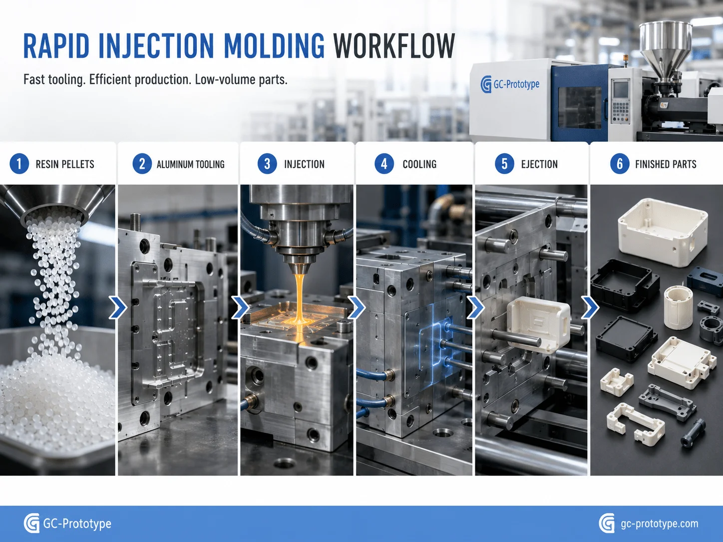
Injection molding heats thermoplastic pellets until they can flow, injects the molten polymer into a metal mold, holds pressure while the material cools, and ejects the finished component. Once a stable process is established, the cycle can be repeated rapidly with excellent consistency.
Traditional production tooling may use hardened steel and multiple cavities to support hundreds of thousands or millions of molding cycles. That approach is appropriate for mature products with predictable demand, but it may be excessive during engineering validation or early market launch.
Rapid injection molding reduces this barrier by using simpler tooling strategies such as aluminum molds, pre-hardened steel inserts, or single-cavity tools. Tool life is lower than a hardened mass-production mold, but initial cost and lead time can be significantly reduced.
A typical project may follow this progression:
3D-printed appearance prototypes
Functional CNC or additive prototypes
DFM and material validation
Rapid injection mold
T0/T1 molding trials
Pilot-production batch
Design and process validation
Production tooling when volume justifies it
This staged approach is particularly useful when a company expects hundreds or several thousand parts but does not yet want to commit to a complex high-cavity tool.
| Manufacturing Route | Tooling Investment | Production Material | Best Use |
| 3D Printing | Very low | Process-dependent | Concepts and early prototypes |
| Vacuum Casting | Low | Polyurethane simulation | 10–100 production-like parts |
| Rapid Injection Molding | Moderate | Real thermoplastics | Pilot and low-volume production |
| Production Injection Molding | High | Real thermoplastics | Stable high-volume manufacturing |
Rapid tooling also provides an important engineering advantage: the parts are produced using the same fundamental molding process and thermoplastic families intended for commercial production. Engineers can evaluate snap fits, weld lines, shrinkage, assembly, chemical resistance, and actual molded behavior before investing in high-volume tooling.
Industry Applications & Material Compliance
Injection molding serves almost every hardware industry because of its broad material selection, repeatability, and production efficiency. Typical applications include medical-device housings, automotive connectors, sensor bodies, consumer-electronics enclosures, robotic covers, industrial controls, laboratory equipment, and structural polymer components.
Material selection should begin with functional requirements rather than resin price alone. Mechanical strength, impact performance, temperature, chemical resistance, dimensional stability, flammability, appearance, sterilization, and regulatory requirements can all influence the final choice.
Medical Innovation: Using biocompatible polymers for medical injection molding
Using biocompatible polymers for medical injection molding requires more than selecting a resin that is marketed for healthcare applications. Medical R&D teams must define the intended device use, contact type, contact duration, sterilization method, cleaning chemicals, mechanical loading, and documentation requirements before choosing the exact material grade.
Common polymer families considered for medical hardware include polycarbonate, medical-grade ABS, polypropylene, PEEK, TPE, selected nylons, and other engineered thermoplastics. Each has a different combination of properties.
Polycarbonate provides impact resistance, dimensional stability, and potential transparency, making it useful for diagnostic housings and selected fluid-management components. Medical-grade ABS can support cost-effective equipment housings where chemical and sterilization requirements allow. Polypropylene offers chemical resistance and can be suitable for disposable components. PEEK provides high temperature performance, excellent chemical resistance, and strong mechanical properties for demanding applications.
Typical molded medical components include:
Diagnostic equipment housings
Laboratory instrument covers
Fluid connectors
Cartridge components
Handheld device shells
Surgical instrument handles
Internal brackets
Buttons and user-interface parts
Disposable medical hardware
Material documentation should be reviewed for the exact resin grade rather than the general polymer family. A standard ABS grade and a specifically documented medical ABS grade are not interchangeable simply because both materials are called ABS.
Colorants, additives, mold-release agents, and regrind strategy can also affect material qualification. Where medical requirements are stringent, manufacturers may need controlled material handling, lot traceability, documented processing conditions, and dedicated production procedures.
The intended sterilization process must also be considered. Steam, ethylene oxide, radiation, and chemical sterilization can affect polymers differently. Mechanical properties, color, dimensions, and environmental stress cracking should be validated using the selected production resin and actual sterilization conditions.
Design Standards: Following an injection molding design guide for medical devices
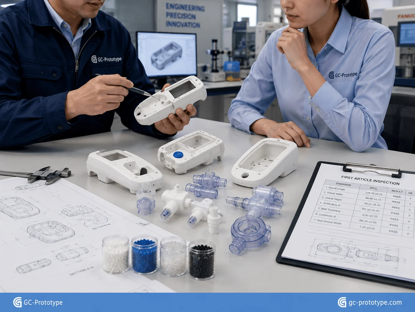
Following an injection molding design guide for medical devices helps Senior Mechanical Engineers reduce molding defects while supporting repeatability, cleanability, and assembly performance.
One of the most important principles is uniform wall thickness. Large transitions from thin walls to heavy sections create uneven cooling. Thick regions cool more slowly and can develop sink marks, internal voids, differential shrinkage, or warpage.
Instead of increasing wall thickness to improve stiffness, engineers should use ribs, gussets, and well-designed bosses. These features can strengthen the component while maintaining more consistent cooling.
Draft is equally important. Molded parts shrink around cores as they cool, creating friction during ejection. Vertical walls should therefore include sufficient draft so that the component can leave the tool without scratches, deformation, or excessive ejector force.
The required draft depends on:
1.Surface texture
2.Depth of the feature
3.Polymer
4.Mold construction
5.Cosmetic requirements
Textured surfaces usually need more draft than polished surfaces because the plastic mechanically engages with the texture.
Sharp internal corners should also be avoided. Rounded transitions improve polymer flow and reduce localized stress. Proper corner radii can improve both molding performance and the durability of the finished product.
Medical equipment may also require cleanable external geometry. Deep uncontrolled crevices, sharp recessed corners, and poorly accessible seams can complicate cleaning. DFM should therefore consider the finished device rather than only whether the component can be molded.
A strong medical DFM review should evaluate:
Wall thickness
Draft angle
Rib proportions
Screw bosses
Snap fits
Parting lines
Gates
Weld lines
Ejector marks
Material selection
Surface finish
Assembly tolerance
Medical-device manufacturers operating under regulated quality systems may require additional validation and documentation. Injection-molding DFM helps establish a manufacturable design, but product compliance depends on the complete device, approved material, manufacturing process, verification strategy, and applicable regulatory requirements.
Process Trade-Offs & Surface Quality
Cost Breakdown: plastic injection molding vs 3d printing cost
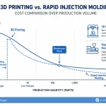
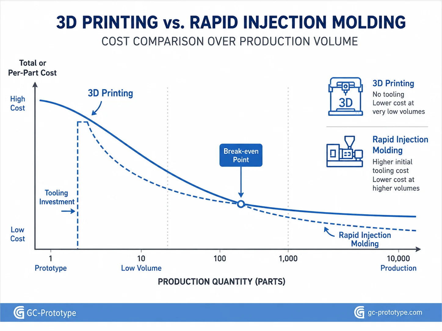
A realistic plastic injection molding vs 3d printing cost comparison must evaluate quantity, tooling, material, part geometry, finishing, engineering revisions, and expected product life.
For one to five pieces, 3D printing is usually the more economical route. There is no dedicated mold, and an updated CAD file can be printed immediately after a design change.
Once demand reaches hundreds or thousands of identical parts, the economics often reverse. Injection molding requires upfront tooling, but each production cycle may create a finished component in seconds or minutes. The tooling cost can then be distributed across the full production quantity.
| Cost Factor | 3D Printing | Rapid Injection Molding |
| Upfront Tooling | Minimal | Moderate |
| CAD Revisions | Very easy | Tool modification may be required |
| 1–5 Parts | Excellent economics | Poor economics |
| 100–1,000 Parts | Geometry-dependent | Often increasingly attractive |
| 1,000–10,000 Parts | Unit cost may remain high | Strong production economics |
| Production Resin | Limited by process | Full thermoplastic selection |
| Surface Repeatability | Process-dependent | Excellent with stable tooling |
| Cycle Time at Scale | Relatively slow | Very efficient |
Consider a consumer-electronics enclosure. Ten SLA prototypes may be economical for early ergonomic testing. If the program then needs 2,000 identical PC/ABS housings, printing each enclosure individually may require considerable machine capacity and finishing.
A rapid injection mold requires a larger initial investment, but the recurring molded-part cost can fall substantially once the tool is amortized.
The true break-even point varies. It depends on:
Mold size
Number of cavities
Resin cost
Part weight
Machine tonnage
Cycle time
Finishing
Inspection
Scrap rate
Production quantity
Expected engineering changes
Procurement teams should evaluate total cost of ownership rather than asking which process has the lowest quoted unit price.
A cheaper printed prototype may be ideal before design freeze. A molded part may provide more value during validation because it uses the intended thermoplastic and production process.
When Rapid Injection Molding Has the Strongest Financial Advantage
Rapid injection molding is particularly effective when the geometry is mostly stable but commercial volume remains uncertain.
Typical applications include:
Engineering validation batches
Clinical evaluation hardware
Market-launch quantities
Bridge production
Investor and customer samples
Pilot automotive builds
Robotics pre-production
Consumer-electronics market testing
Instead of purchasing a complex hardened multi-cavity mold, a company may use a single-cavity aluminum tool to produce hundreds or several thousand parts. If the design changes, modifying or replacing the simpler tool may involve less financial exposure than revising a high-cost production mold.
Once demand becomes predictable, the project can transition to hardened steel, additional cavities, hot runners, or automated molding.
Surface Finish & Cosmetic Control
Aesthetic Excellence: Achieving Production-Grade custom injection molding surface finish spi standards
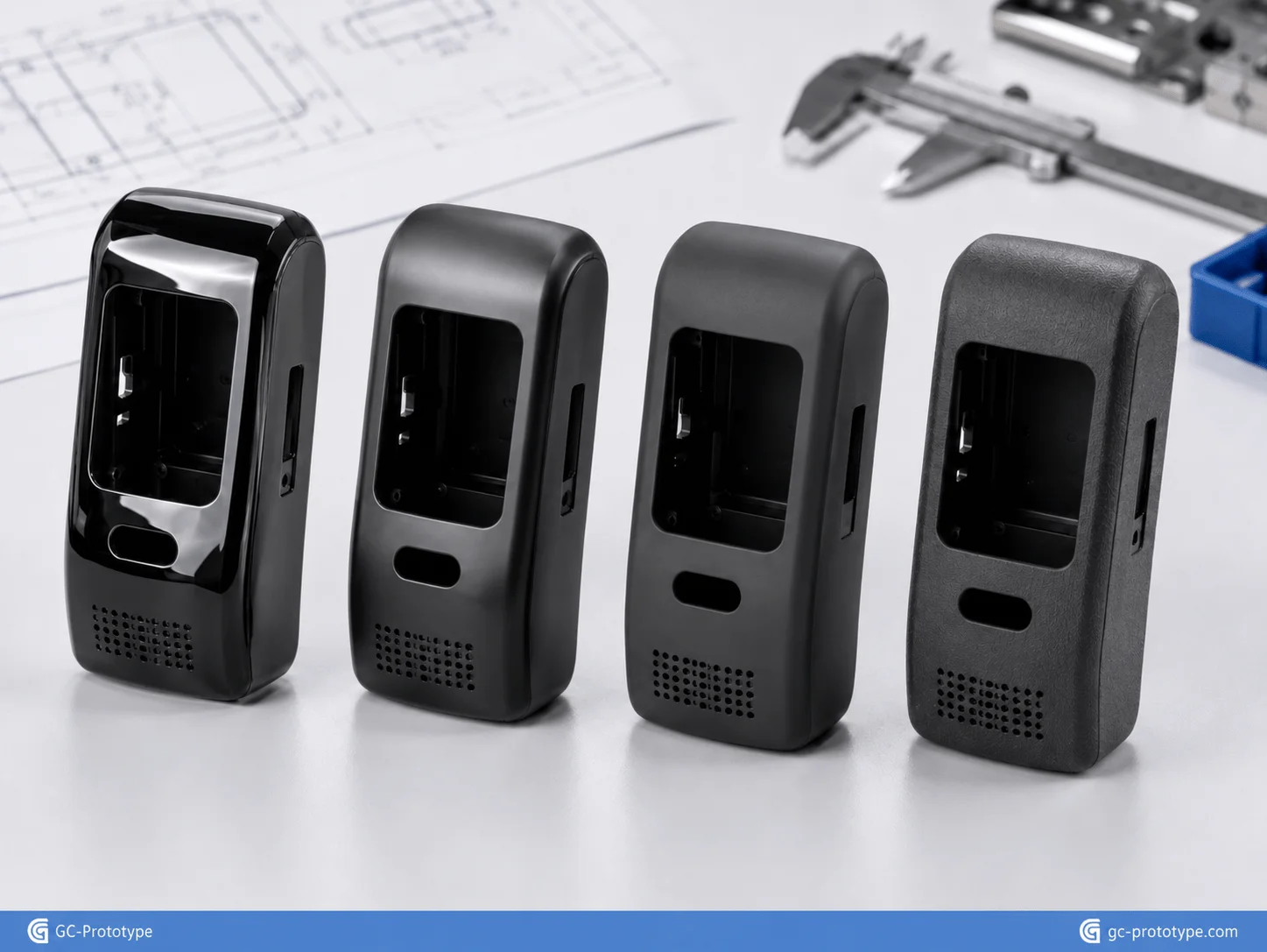
Specifying custom injection molding surface finish spi standards allows Product Designers and Industrialization Engineers to communicate the required mold-surface quality more consistently.
Injection-molded appearance begins with the tool. Plastic replicates the mold cavity surface closely, so polishing, grinding, texturing, and tool marks all influence the final component.
SPI mold-finishing categories are commonly grouped into polished, semi-gloss, matte, and textured finishes. Typical examples include highly polished A-series finishes, B-series paper finishes, C-series stone finishes, and D-series blasted textures.
| Finish Category | General Appearance | Typical Application |
| SPI A | High gloss / polished | Transparent parts and premium surfaces |
| SPI B | Smooth semi-gloss | Consumer electronics |
| SPI C | Fine matte / stone | Industrial housings |
| SPI D | Textured / blasted | Grips and non-gloss surfaces |
An SPI A-2 surface may be selected for a premium glossy housing or selected transparent component, while SPI B-1 may provide a controlled smooth finish without mirror polishing. The correct choice should be agreed with the moldmaker because polishing difficulty depends on tool steel, geometry, access, and required appearance.
Texture changes more than aesthetics. It can influence:
Required draft
Mold-release behavior
Visible flow marks
Scratch resistance
Grip
Paint adhesion
Fingerprint visibility
Deep textures require additional draft. Failure to account for this can cause drag marks or ejection damage.
Cosmetic quality also depends on gate position and weld lines. A perfectly polished cavity cannot compensate for a poorly located gate that creates a visible flow mark across a Class-A surface.
For appearance-critical parts, the drawing should identify:
Class-A surfaces
Approved SPI finish
Texture reference
Color
Gloss
Gate restrictions
Ejector-mark restrictions
Parting-line limits
Physical color and texture samples are often valuable because written descriptions such as “fine matte” can be interpreted differently by engineering, design, and manufacturing teams.
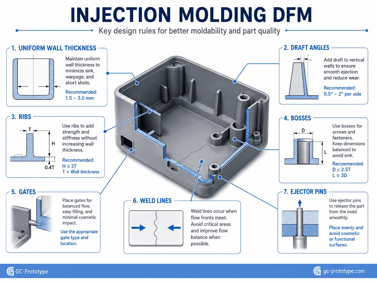
Essential Injection Molding DFM Rules
Effective DFM is one of the fastest ways to lower mold cost, shorten lead time, and improve first-pass part quality.
Maintain Uniform Wall Thickness
Uniform walls promote balanced filling and cooling. Thick isolated sections should be cored out where possible.
A heavy screw boss connected directly to a thin cosmetic wall may cause sink on the opposite surface. Ribs and gussets can provide support with less material.
Add Practical Draft Angles
Draft should be incorporated early instead of added after industrial design is complete. Deep ribs, internal walls, and textured surfaces deserve special attention.
Design Ribs Carefully
Ribs should reinforce walls without becoming thick enough to create sink. Their thickness, height, spacing, and root radius should be matched to the resin and structural requirement.
Design Bosses for Fasteners
Screw bosses require sufficient wall thickness and support but should avoid excessive mass. Connecting bosses to nearby walls using ribs is often more efficient than creating a solid section.
Threaded metal inserts can be installed ultrasonically, thermally, or through insert molding when repeated assembly requires higher thread strength.
Manage Undercuts
Undercuts may require slides, lifters, collapsible cores, or other moving tooling. Every side action increases mold complexity, cost, maintenance, and lead time.
A design review should determine whether the undercut can be eliminated, moved, redesigned as a snap feature, or created with a secondary operation.
Control Gates and Weld Lines
Gate location influences filling, packing, shrinkage, and cosmetic appearance. Weld lines form where separate flow fronts meet and may become structural weak points.
Critical snap fits, pressure features, or highly loaded sections should not be placed directly on uncontrolled weld lines where possible.
Design for Ejection
Ejector pins must apply enough force to release the part without creating excessive witness marks or deformation. Cosmetic surfaces should remain free of visible ejector marks when possible.
| DFM Issue | Potential Defect | Recommended Strategy |
| Thick isolated wall | Sink and voids | Core out section |
| Insufficient draft | Ejection damage | Add draft |
| Heavy rib | Surface sink | Reduce rib thickness |
| Deep undercut | Expensive tooling | Simplify or use secondary operation |
| Poor gate location | Weld lines / appearance issues | Optimize flow path |
| Sharp internal corner | Stress and poor flow | Add radii |
Procurement Strategy & Scaling
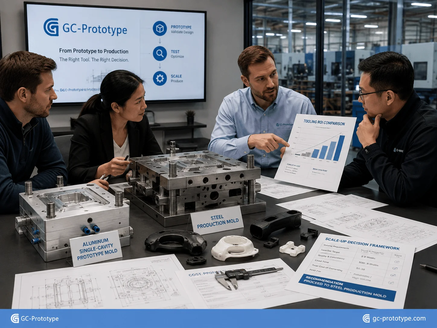
Financial Edge: Tooling ROI & Aluminum Mold Strategy
For Procurement Managers, Strategic Buyers, and Sourcing Managers, tooling should be evaluated as an investment rather than simply an upfront expense.
A production mold designed for one million cycles makes little sense for a product expected to sell only 2,000 units. Conversely, repeatedly purchasing expensive low-volume prototypes can become wasteful when commercial demand is already proven.
Aluminum tooling often provides an attractive intermediate strategy.
Potential advantages include:
Lower tooling investment
Faster mold manufacture
Easier engineering changes
Suitable life for pilot production
Production-grade thermoplastics
Shorter path to market
Aluminum tooling does have limitations. It is softer than hardened steel and may wear more quickly with abrasive glass-filled resins or high-volume production. Complex slides, deep textures, and demanding tolerances may also favor steel.
The correct decision depends on expected lifetime volume and resin.
Understanding Tooling Cost Drivers
Mold quotation cost is influenced by:
Part dimensions
Cavity count
Mold steel or aluminum
Side actions
Hot runner systems
Surface finish
Texture
Tolerances
Cooling system
Inserts
Tool life target
| Cost Driver | Effect on Tooling | Cost-Control Strategy |
| Multiple cavities | Higher upfront tool cost | Add cavities after demand is proven |
| Slides/lifters | More complexity | Reduce undercuts |
| High-polish finish | More polishing labor | Restrict to Class-A zones |
| Tight tolerances | More precision machining | Apply functionally |
| Abrasive resin | Higher wear requirement | Select suitable tool material |
| Complex cooling | Higher design/manufacturing cost | Justify with cycle-time savings |
Scaling from 100 to 10,000 Parts
For quantities around 100 parts, a simple single-cavity tool may offer the lowest financial risk.
At 1,000–5,000 parts, the buyer may justify improved cooling, automated ejection, or additional cavities.
At 10,000 units and beyond, a more durable steel mold may provide lower lifetime cost.
There is no single quantity threshold that applies to every project. A small PP clip and a large PC/ABS enclosure have completely different tooling and cycle economics.
Procurement teams should request several quotation scenarios rather than only one:
100 parts
500 parts
1,000 parts
5,000 parts
10,000 parts
This allows the engineering and sourcing teams to identify the production strategy that provides the best return on tooling investment.
Application Scenarios
Medical Diagnostic Housing
A medical-device team completes several SLA prototypes and needs 500 production-intent housings for functional validation. A rapid aluminum mold provides actual PC/ABS parts with controlled surfaces and repeatable snap-fit geometry.
Fluid Connector
A healthcare hardware manufacturer needs several thousand molded connectors in a qualified polymer. Tooling DFM focuses on sealing geometry, flow path, weld lines, and critical dimensions.
Consumer Electronics Enclosure
A smart-device company needs 2,000 premium housings for market launch. Rapid molding reproduces the selected SPI surface finish and consistent color while avoiding a high-cavity production mold before sales demand is confirmed.
Automotive Sensor Housing
An automotive supplier needs pilot-production sensor housings for validation. The mold produces stable interfaces and allows engineers to evaluate the actual production resin before full production tooling.
Robotics Controller Cover
A robotics manufacturer transitions from 3D-printed covers to injection-molded PC/ABS parts after annual demand increases. Ribs improve stiffness while molded bosses simplify assembly.
Industrial Automation Component
An industrial equipment manufacturer needs repeat batches of machine covers and electrical housings. Low-volume molding provides consistent components without carrying excessive finished inventory.
Selecting an Injection Molding Supplier
A capable supplier should support more than mold manufacturing. The strongest manufacturing partners integrate DFM, tooling, molding, secondary operations, quality control, and scale-up planning.
Important capabilities include:
Material-selection support
Injection molding DFM
Mold-flow analysis when justified
Aluminum and steel tooling
Tool sampling
Process optimization
Insert molding
Overmolding
Surface finishing
Printing and laser marking
Dimensional inspection
Assembly
Tool maintenance
A complete RFQ should include:
3D CAD file
2D drawing
Material grade
Quantity forecast
Lifetime volume
Surface finish
Color
Critical dimensions
Cosmetic zones
Inserts
Inspection requirements
Packaging expectations
Before tooling starts, the supplier should identify draft problems, undercuts, sink risks, likely weld lines, gate locations, cosmetic limitations, and expected tooling life.
For medical and other controlled applications, resin documentation and material traceability should also be agreed before production.
Frequently Asked Questions
What Is Rapid Injection Molding?
Rapid injection molding uses simplified or faster-produced tooling, frequently aluminum or softer steel, to manufacture real injection-molded thermoplastic parts for prototypes, pilot production, and lower-volume manufacturing.
When Is Injection Molding Better Than 3D Printing?
Injection molding becomes increasingly attractive when the design is stable, identical part quantities rise, and production thermoplastic properties or repeatable surfaces are required.
Are Injection-Molded Parts Stronger Than 3D-Printed Parts?
They can provide more isotropic and production-representative material behavior, but actual performance depends on resin, geometry, molding conditions, and the additive process being compared.
What Materials Are Used for Medical Injection Molding?
Depending on the application, manufacturers may consider PC, PP, medical ABS, PEEK, TPE, nylon, and other documented polymer grades.
What Does SPI Surface Finish Mean?
SPI finish classifications provide commonly used references for polished, semi-gloss, matte, and textured injection-mold surfaces.
Can Aluminum Molds Produce Production Parts?
Yes. Aluminum molds can manufacture production-grade thermoplastic parts and are commonly used for prototypes, pilot production, and selected low- to medium-volume programs.
How Many Parts Can an Aluminum Mold Produce?
Tool life depends on alloy, polymer, glass-fiber content, part geometry, pressure, maintenance, and mold construction. It should be estimated specifically for the project.
How Can Injection Mold Cost Be Reduced?
Reduce unnecessary undercuts, use practical tolerances, simplify surface requirements, standardize materials, avoid excessive mold actions, and choose tooling life appropriate to forecast volume.
When Should a Company Upgrade to Steel Tooling?
Steel tooling becomes more attractive as production volume, abrasive material use, automation requirements, or expected tool life increases.
What Files Are Needed for a Quote?
Provide 3D CAD files, drawings, material requirements, quantities, surface finish, color, tolerances, inserts, inspection requirements, and expected lifetime production.
Injection molding provides one of the most effective routes for moving plastic hardware from functional prototypes into scalable commercial manufacturing. Rapid tooling fills the critical gap between additive prototypes and expensive high-volume production molds, allowing engineering teams to validate actual thermoplastics, molded geometry, assembly performance, surface quality, and market demand before committing to major tooling investment.
The strongest programs combine appropriate production polymers, uniform walls, practical draft, efficient ribs and bosses, realistic tolerances, controlled cosmetic standards, and a tooling strategy matched to forecast volume.
For medical devices, consumer electronics, automotive sensors, robotics, and industrial automation, aluminum or simplified tooling can provide a practical route from hundreds of pilot components to thousands of production parts while keeping early-stage capital exposure under control.
Scaling from a single functional prototype to a pre-production run shouldn’t deplete your R&D budget. Whether you are a Senior Mechanical Engineer developing healthcare enclosures or a Sourcing Manager seeking cost-effective plastic molding alternatives, GC Prototype delivers.