Address:
Shenzhen Bao'an District Xinqiao Subdistrict Huangpu Community Huangpu East Ring Road No. 504 Shenzhen Yuan Industrial City Building C
Work Hours:
Monday to Friday: 9AM - 21PM
Weekend: 9AM - 21PM

Address:
Shenzhen Bao'an District Xinqiao Subdistrict Huangpu Community Huangpu East Ring Road No. 504 Shenzhen Yuan Industrial City Building C
Work Hours:
Monday to Friday: 9AM - 21PM
Weekend: 9AM - 21PM

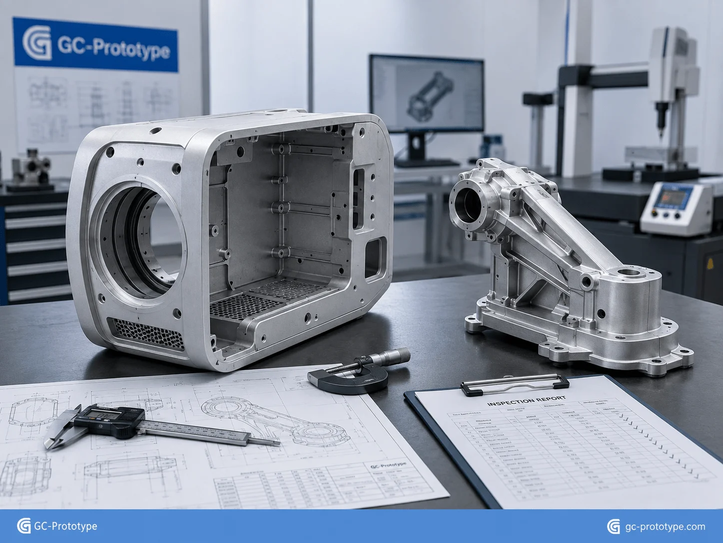
Pressure Die Casting is one of the most efficient manufacturing processes for moving complex metal hardware from New Product Introduction (NPI) into repeatable medium- and high-volume production. When 3D printing or CNC machining becomes too expensive at scale and conventional sand casting cannot deliver the required dimensional consistency or surface quality, pressure die casting offers a practical combination of high productivity, near-net-shape geometry, thin-wall capability, and lower recurring unit cost.
For Senior Mechanical Engineers, Product Designers, Manufacturing Engineers, and Sourcing Managers, successful die casting depends on decisions made long before tooling starts. Alloy selection, wall thickness, draft, porosity control, tolerance planning, machining allowances, tooling complexity, expected production volume, and surface finishing all influence total cost of ownership. This guide follows the material-selection, process-comparison, precision-control, and procurement framework defined in the project outline.
Why Pressure Die Casting Works for Production Hardware
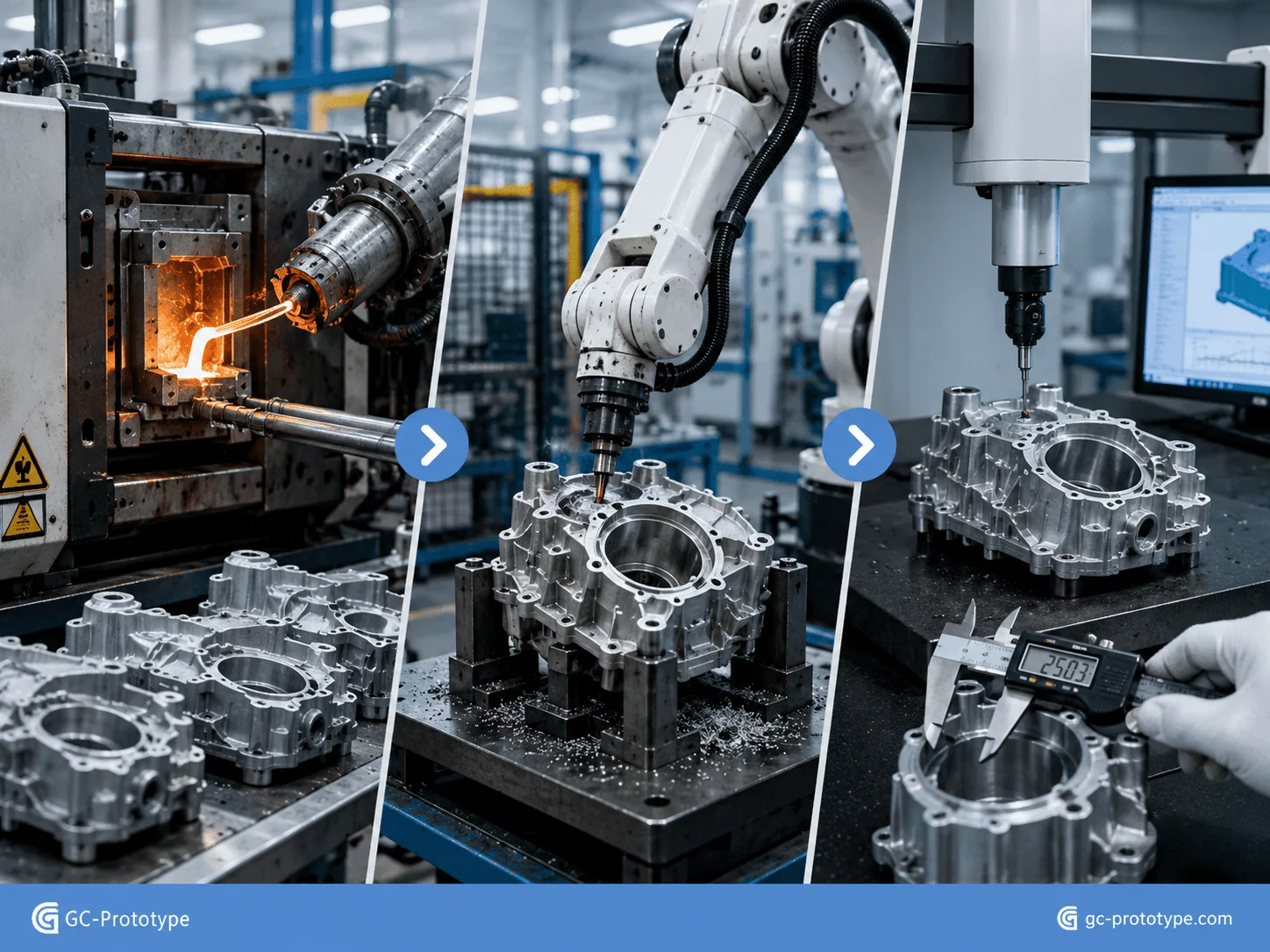
Pressure die casting injects molten nonferrous metal into a precision steel die under high pressure. Once the cavity is filled, the alloy rapidly solidifies before the die opens and ejects the casting. Gates, runners, flash, and overflows are then removed before secondary machining, finishing, inspection, and assembly.
The high initial tooling investment is the key economic difference between pressure die casting and prototype-oriented manufacturing processes. A dedicated die requires engineering, tool steel, machining, inserts, slides where necessary, cooling circuits, ejection systems, and validation. Once that investment has been made, however, the process can produce large numbers of repeatable parts using relatively short cycle times.
This makes pressure die casting particularly attractive for:
Structural housings
Motor and gearbox enclosures
Electronic control housings
Medical equipment frames
Robotic joint bodies
Heat-management components
Automotive sensor housings
Industrial machine brackets
Consumer electronics chassis
A major advantage is part consolidation. Features that would otherwise require several machined or fabricated components can sometimes be integrated into one casting. Ribs, mounting bosses, external fins, cable channels, pockets, and assembly interfaces can be designed directly into the part.
| Manufacturing Process | Upfront Tooling | Unit Cost at Scale | Dimensional Repeatability | Best Fit |
|---|---|---|---|---|
| CNC Machining | Low | High | Excellent | Prototypes and low volume |
| Sand Casting | Low to moderate | Moderate | Moderate | Large, lower-volume castings |
| Pressure Die Casting | High | Low at volume | High | Medium- to high-volume production |
| Metal 3D Printing | Very low | High | Process-dependent | Complex prototypes and specialized parts |
Industry Applications & Material Compliance
Material selection in pressure die casting should begin with functional requirements rather than raw-material price alone. Engineers need to evaluate structural loading, operating temperature, corrosion exposure, thermal management, surface finishing, secondary machining, and documentation requirements.
Aluminum alloys are widely used because they combine relatively low density with stiffness, corrosion resistance, and useful thermal conductivity. Zinc alloys can provide excellent filling behavior for small detailed components, while magnesium offers a very low-density option for weight-sensitive applications.
For many industrial and electronic housings, aluminum alloys such as A380 and ADC12 are common starting points because they support complex cast geometry and economical production. The final material should still be selected against the actual performance specification.
Medical Innovation: Incorporating pressure die casting design guidelines for medical devices
Applying pressure die casting design guidelines for medical devices requires engineering teams to consider structural performance, cleanability, corrosion resistance, surface treatment, assembly, and the intended role of the component.
Typical die-cast applications in medical equipment may include imaging-system housings, diagnostic-machine frames, robotic surgery supports, motor housings, monitor brackets, internal structural components, and equipment covers. These are generally structural or equipment-level parts rather than implantable components.
Medical equipment frequently requires smooth, cleanable surfaces and resistance to repeated cleaning. Geometry should therefore minimize unnecessary dirt traps, uncontrolled seams, and inaccessible recesses. Rounded transitions and well-defined finishing zones can simplify both manufacturing and cleaning.
Aluminum alloys such as A380 or ADC12 may provide an effective balance of weight, stiffness, corrosion performance, and manufacturing efficiency for suitable medical hardware. Surface treatments or coatings can further improve corrosion resistance and appearance, but coating selection should be matched to the intended cleaning environment.
Critical design considerations include:
Uniform wall thickness
Practical draft angles
Smooth external transitions
Controlled parting lines
Machined sealing or mounting surfaces
Appropriate corrosion protection
Clearly defined cosmetic zones
Material traceability where required
Dimensional inspection of critical interfaces
Porosity also matters. Pressure die casting can contain internal gas or shrinkage porosity. For a simple equipment cover, small internal pores may have little functional consequence. For a housing that requires leak-tight passages or deeply machined sealing interfaces, porosity becomes a much more important engineering concern.
The safest approach is to define the real functional requirement on the drawing and allow the supplier to recommend process controls, machining allowances, inspection, and leak testing where needed.
Process Trade-Offs & Precision Standards
Cost Breakdown: pressure die casting vs sand casting cost comparison
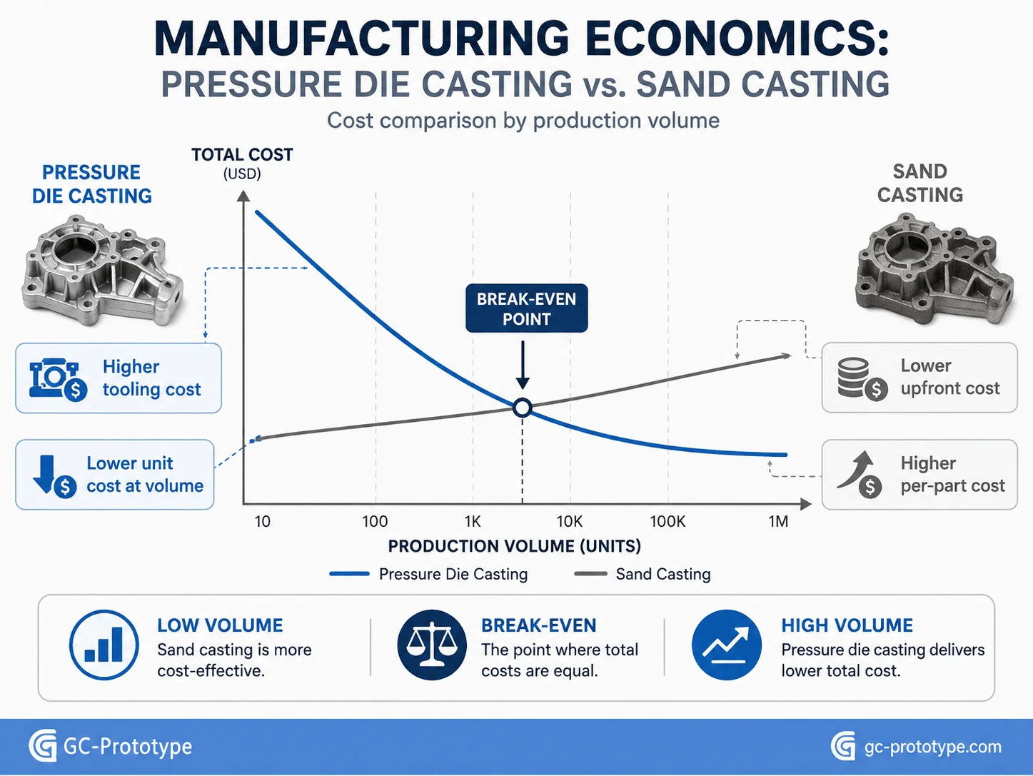
A practical pressure die casting vs sand casting cost comparison must look beyond the initial tooling quotation. Sand casting normally requires less expensive tooling, which makes it attractive for prototypes, large components, uncertain demand, and relatively low annual quantities.
Pressure die casting requires much more sophisticated tooling. The steel die must survive repeated thermal cycling and injection pressure while maintaining dimensional consistency. Slides, inserts, cooling channels, trim tooling, and polishing can further increase the initial investment.
Once production volume rises, the economic picture changes.
Pressure die casting can achieve short production cycles and near-net-shape geometry, which can reduce both labor and secondary CNC machining. If thousands or tens of thousands of identical parts are required, the tooling investment can be distributed across a much larger quantity.
| Cost Factor | Pressure Die Casting | Sand Casting |
|---|---|---|
| Tooling Investment | High | Low to moderate |
| Production Rate | High | Lower |
| Unit Cost at Volume | Low | Moderate |
| Surface Quality | Generally smoother | Generally rougher |
| Thin-Wall Capability | Strong | More limited |
| Secondary Machining | Often reduced | Often greater |
| Design Change Cost | High after tooling | Lower |
| Best Economic Fit | Stable medium/high volume | Prototype and lower volume |
The break-even point is project-specific. There is no universal quantity at which pressure die casting automatically becomes cheaper.
A purchasing team should evaluate:
Tooling cost
Expected annual volume
Product lifetime
Casting cycle time
Material consumption
Scrap rate
CNC machining
Surface finishing
Inspection
Tool maintenance
Engineering-change risk
For example, a product expected to sell only a few hundred units may not justify a complex production die. A stable robotics enclosure with forecast demand in the thousands could produce a very different financial result.
Total cost of ownership is therefore more useful than comparing casting price alone. A cheap sand casting that requires extensive machining, grinding, and finishing can ultimately cost more than a more expensive die-cast tool with a much lower recurring unit cost.
Near-Net-Shape Manufacturing and Secondary Machining
One of the financial advantages of pressure die casting is its ability to place significant geometry directly into the casting.
Ribs, external fins, mounting bosses, cable guides, and many holes or recesses can be produced as part of the die geometry. This reduces the amount of material that must be removed later.
However, critical bearing bores, sealing faces, threaded features, precision locating datums, and high-accuracy interfaces may still require CNC machining. The goal is not to eliminate machining completely, but to apply it only where function demands greater precision than the as-cast process can economically provide.
Engineering Precision & Quality Control
Engineering Precision: Understanding pressure die casting tolerance standards ISO 8062
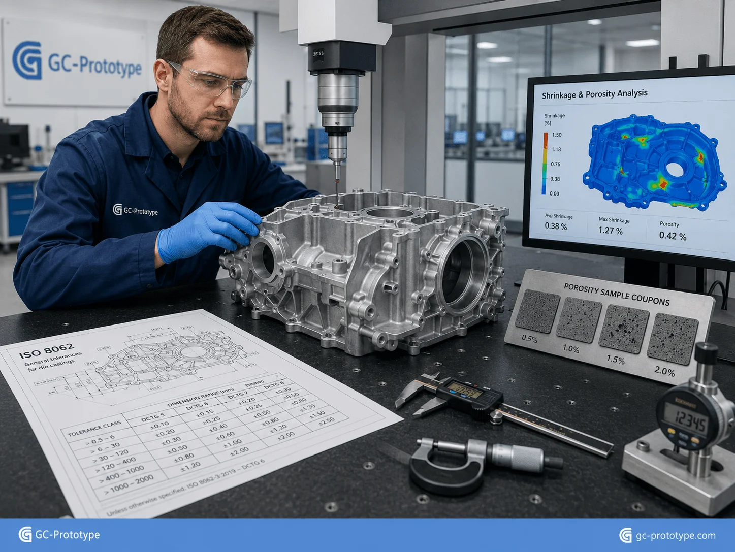
Understanding pressure die casting tolerance standards ISO 8062 helps Product Designers, Quality Engineers, and Industrialization Engineers communicate realistic casting requirements without forcing unnecessary CNC-level precision onto every feature.
Casting tolerances are influenced by many variables, including part size, alloy behavior, die construction, parting-line location, slides, wall thickness, thermal conditions, shrinkage, and tool wear. ISO 8062 provides a structured framework for specifying dimensional and geometrical tolerances for cast parts, but the correct tolerance strategy still needs to reflect the specific casting process and supplier capability.
A practical engineering drawing should separate:
General as-cast dimensions
Critical functional dimensions
Machined dimensions
Datum relationships
Mating interfaces
Surface requirements
Inspection requirements
Assigning extremely tight tolerances to every wall and rib increases manufacturing cost without necessarily improving product performance.
Managing Shrinkage
Molten aluminum contracts as it cools and solidifies. Tool designers account for this behavior when determining cavity dimensions, but shrinkage is not determined by one number alone.
Geometry, local wall thickness, metal flow, die temperature, alloy, cooling, and surrounding features influence actual dimensional behavior.
Designers should therefore avoid trying to independently scale an entire CAD model based on a generic shrinkage percentage. The casting supplier normally manages tool compensation using material data, manufacturing experience, and sample measurement.
Production-intent samples are then inspected and the tool can be adjusted where appropriate.
Porosity Control
Porosity is one of the most discussed quality issues in pressure die casting. It can result from trapped gas, shrinkage, turbulence, or process conditions during filling and solidification.
The importance of porosity depends on where it occurs and what the part must do.
For cosmetic covers, limited internal porosity may be acceptable. For pressure-sensitive housings, sealing surfaces, deeply machined areas, or highly loaded structures, the acceptance criteria may need to be stricter.
Quality strategies may include:
Gate and runner optimization
Venting and overflow design
Stable die temperature
Controlled melt handling
Vacuum-assisted casting where appropriate
X-ray or other internal inspection
Leak testing
Controlled machining depth
Fit Tolerances and Machining Allowances
Engineers should identify which features genuinely need secondary machining before tooling begins.
Bearing seats, precision bores, gasket surfaces, tapped holes, and locating datums may require machining stock. If insufficient stock is designed into the casting, machining may expose porosity or fail to clean up the surface completely.
Conversely, excessive machining allowance wastes material and machine time.
A DFM review should therefore connect casting design and CNC finishing as one manufacturing system.
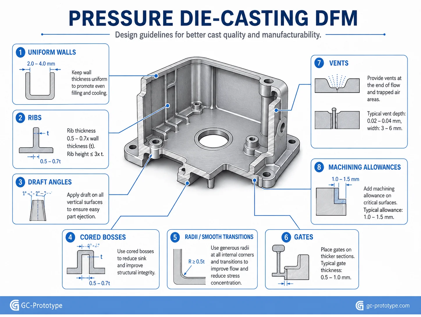
Essential DFM Rules for Pressure Die Casting
Good pressure die-casting DFM improves filling, reduces distortion, protects the tool, and lowers recurring production cost.
Maintain Uniform Wall Thickness
Large differences between thick and thin sections can create uneven cooling and shrinkage. Heavy areas may also become porosity hot spots.
Where practical, core out heavy sections and use ribs to provide stiffness without creating unnecessary mass.
Use Practical Draft Angles
Castings need to release from the die after solidification. Draft reduces friction between the part and the tool during ejection.
Deep walls, textured surfaces, and internal features often require more draft than shallow external surfaces. Zero-draft requirements should be limited to genuinely critical areas.
Use Ribs Instead of Heavy Solid Sections
Ribs increase structural stiffness without requiring a thick wall. They are especially useful for robotic housings, motor enclosures, electronic covers, and industrial brackets.
Rib intersections should transition smoothly to surrounding walls to reduce local hot spots.
Add Radii to Sharp Corners
Sharp internal corners can restrict metal flow and create stress concentrations in both the casting and the tool.
Rounded transitions improve filling and generally produce more durable tooling.
Control Undercuts and Side Actions
Side undercuts may require slides or moving cores in the die. These mechanisms increase tooling cost, manufacturing complexity, maintenance, and potential tolerance variation.
Design teams should determine whether an undercut can be:
1.Eliminated
2.Reoriented
3.Machined afterward
4.Replaced by an assembly feature
Plan Gates, Vents, and Overflows
The casting must fill rapidly and release displaced air. Gate, runner, vent, and overflow locations therefore influence surface quality, porosity, and filling consistency.
Product designers do not normally design the entire runner system themselves, but they should leave adequate space around the component and avoid placing critical surfaces where gate removal or overflow trimming creates unnecessary risk.
| DFM Problem | Manufacturing Risk | Preferred Response |
|---|---|---|
| Thick isolated boss | Porosity and shrinkage | Core out and reinforce with ribs |
| No draft | Difficult ejection | Add practical draft |
| Sharp internal corner | Poor filling and tool stress | Add radius |
| Multiple side undercuts | Expensive die slides | Simplify or machine afterward |
| Tight tolerance everywhere | High cost and rework | Prioritize critical features |
| Heavy machining allowance | Waste and porosity exposure | Optimize stock locally |
Procurement Strategy & Scaling
Financial Edge: high precision aluminum die casting for robotics
Sourcing high precision aluminum die casting for robotics can provide a strong economic and engineering advantage once robotic hardware moves from prototype validation into repeat production.
Robot joints, actuator housings, motor covers, controller enclosures, gearbox bodies, and structural interfaces often need several characteristics simultaneously:
High stiffness
Low weight
Thin-wall geometry
Thermal conductivity
Stable mounting interfaces
Integrated ribs
Repeatable assembly
Attractive industrial appearance
During early development, these parts may be CNC machined from aluminum because design changes are frequent and no tooling is required. Once the mechanical architecture is validated, continued machining can become expensive.
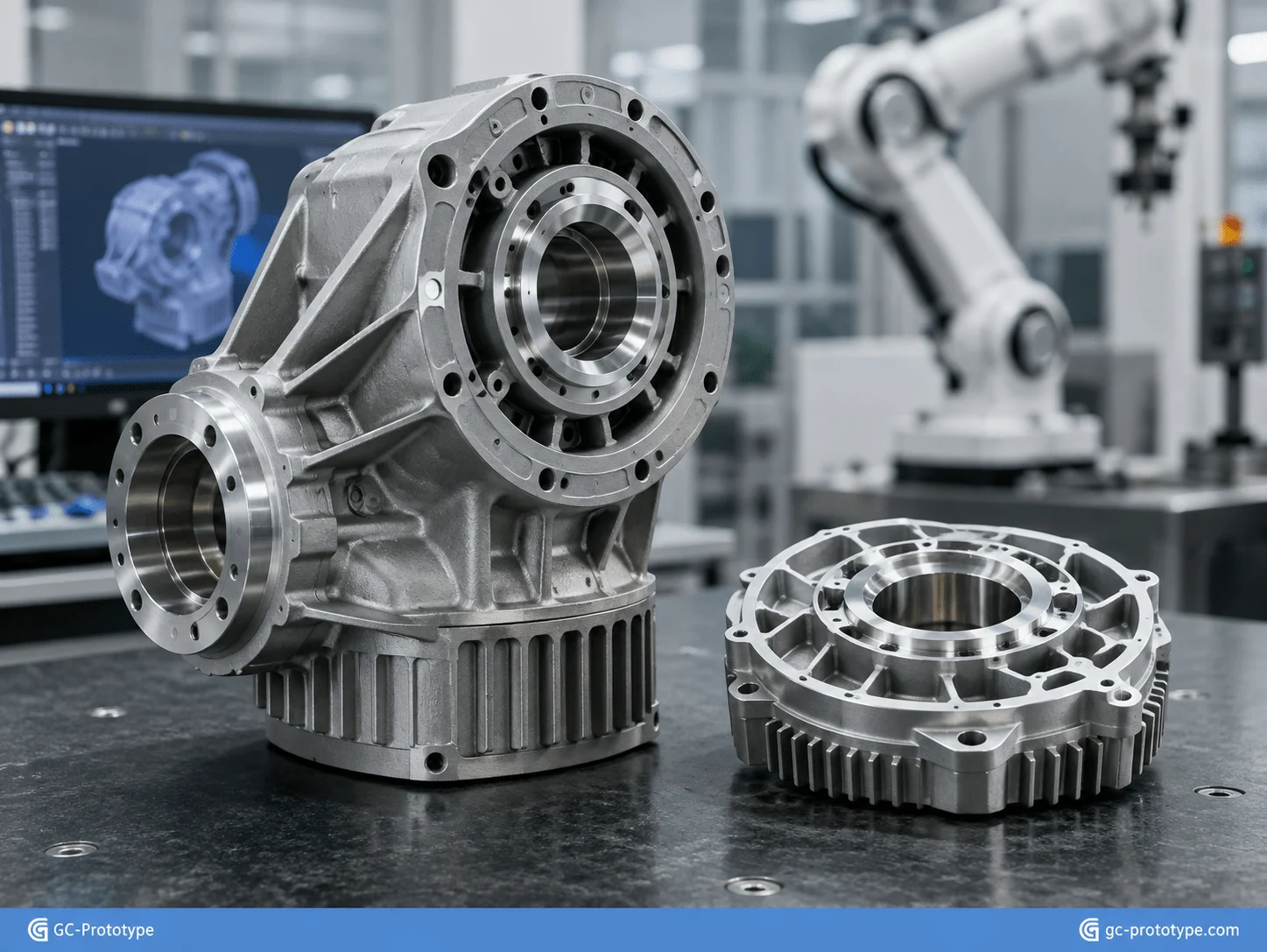
Die casting can integrate ribs, fins, bosses, mounting points, and external geometry into one near-net-shape component. CNC machining can then be limited to bearing bores, alignment datums, sealing faces, or other critical interfaces.
This hybrid strategy often provides better total economics than machining the entire component from billet.
Robotics Example: Motor Housing
Consider a robotic motor housing with external cooling fins, an internal cylindrical motor interface, four mounting bosses, and cable-routing features.
A billet-machined version may require:
1.Large starting stock
2.Extensive material removal
3.Several milling operations
4.Long machine time
5.Multiple tool changes
A die-cast version can create most of the external and internal structure directly in the mold. Only the precision motor bore and mounting interfaces may need subsequent machining.
The result can be shorter recurring cycle time and less material waste once volume supports the tooling investment.
Cost Structure for Procurement Teams
A transparent die-casting quotation should separate one-time and recurring costs.
| Cost Element | One-Time or Recurring | Procurement Consideration |
|---|---|---|
| Die design | One-time | Complexity and tool life |
| Production die | One-time | Cavities, slides, inserts |
| Trim tooling | One-time | Required after casting |
| Casting material | Recurring | Alloy and weight |
| Machine cycle | Recurring | Part size and productivity |
| CNC finishing | Recurring | Critical features only |
| Surface treatment | Recurring | Cosmetic/corrosion requirement |
| Inspection | Recurring | Quality-plan intensity |
| Tool maintenance | Periodic | Include ownership terms |
Purchasing Managers should request volume-based quotations rather than a single quantity. Comparing 1,000, 5,000, 10,000, and larger lifetime quantities can reveal how tooling amortization affects total program cost.
When Pressure Die Casting Is the Wrong Choice
Pressure die casting is not automatically the best process for every metal part.
CNC machining may remain superior when:
Quantity is very low
Geometry changes frequently
Extremely tight tolerances dominate the design
A specialty alloy cannot be economically die cast
Tooling cannot be amortized
Sand casting may remain attractive for very large, low-volume components.
The manufacturing process should therefore follow product requirements and lifetime economics rather than volume assumptions alone.
Application Scenarios
Medical Imaging Equipment Housing
A medical equipment manufacturer needs a lightweight aluminum enclosure that supports internal electronics and withstands repeated cleaning. Die casting integrates ribs, mounting bosses, and cable-routing features while CNC machining finishes the critical assembly interfaces.
Robotic Joint Housing
A robotics company replaces a heavily machined aluminum housing with a die-cast design after market demand becomes predictable. Integral cooling fins and stiffening ribs reduce secondary machining while preserving structural rigidity.
Automotive Electronic Enclosure
An automotive supplier uses aluminum die casting for an electronic housing requiring thermal management, repeatable mounting features, and large-volume output.
Consumer Electronics Chassis
A smart-hardware manufacturer uses a thin-wall aluminum casting to combine internal structural support, external appearance, and thermal spreading in one component.
Industrial Automation Motor Cover
An automation-equipment company needs repeatable motor covers and gearbox housings for several machine models. Die casting provides consistent geometry, while machined bores and threaded features maintain assembly precision.
Selecting a Pressure Die Casting Supplier
A reliable supplier should provide more than basic casting capacity. The strongest manufacturing partners support the entire process from DFM through finished-part inspection.
Capabilities to evaluate include:
Alloy selection support
Die-casting DFM
Tool design and manufacture
Mold-flow or filling analysis
Trial sampling
Production casting
CNC machining
Deburring and trimming
Surface finishing
Leak testing where required
Dimensional inspection
Tool maintenance
The RFQ package should include a solid 3D CAD model, 2D drawing, material requirement, production forecast, critical tolerances, machining requirements, finish, cosmetic zones, porosity expectations, inspection requirements, and delivery schedule.
Before tooling release, the supplier should clearly explain:
Proposed parting line
Draft requirements
Gate strategy
Expected machining areas
Potential porosity risks
Tool slides or inserts
Critical tolerance capability
Estimated tooling life
Tool ownership and maintenance terms
This early collaboration is particularly important because engineering changes become more expensive after the production die has been manufactured.
Frequently Asked Questions
What Is Pressure Die Casting Best Used For?
Pressure die casting is best suited to repeat production of complex nonferrous metal components such as housings, brackets, covers, motor bodies, electronic enclosures, and structural parts.
Which Aluminum Alloys Are Commonly Used?
A380 and ADC12 are commonly considered for general aluminum die-casting applications. Final alloy selection should depend on mechanical, thermal, corrosion, machining, and finishing requirements.
Is Pressure Die Casting Suitable for Medical Devices?
It can be suitable for medical-equipment housings, frames, robotic supports, and other structural hardware. Suitability depends on the component’s function, cleaning environment, material requirements, and applicable device-level requirements.
Is Pressure Die Casting Cheaper Than Sand Casting?
Not at every volume. Sand casting has lower initial tooling costs, while pressure die casting can provide lower recurring unit cost at higher production volumes.
How Accurate Is Pressure Die Casting?
Accuracy depends on part size, geometry, alloy, die construction, parting lines, slides, process control, and tolerance requirements. Critical features may require secondary CNC machining.
What Is ISO 8062 Used For?
ISO 8062 provides a framework for specifying dimensional and geometrical tolerances for cast parts. Engineers should combine the applicable casting tolerance strategy with supplier capability and individually specified critical features.
Can Die-Cast Parts Contain Porosity?
Yes. Gas and shrinkage porosity can occur in pressure die casting. Its importance depends on location and function, and it can be managed through design, process control, inspection, and machining strategy.
How Can Pressure Die Casting Cost Be Reduced?
Maintain uniform walls, reduce unnecessary slides and undercuts, use ribs instead of heavy sections, apply tight tolerances selectively, and minimize secondary CNC machining.
When Should a Project Move from CNC Machining to Die Casting?
The transition normally makes sense once the design is stable and forecast production volume is high enough for lower recurring casting cost to offset the tooling investment.
What Files Are Needed for a Pressure Die Casting Quote?
Provide 3D CAD files, dimensioned drawings, alloy requirements, quantities, tolerances, machining requirements, finish specifications, inspection needs, and expected production volume.
Pressure die casting is a powerful manufacturing process for converting validated metal hardware into scalable commercial production. Its value comes from high productivity, near-net-shape manufacturing, thin-wall capability, part consolidation, and the ability to reduce recurring CNC machining once production volume justifies dedicated tooling.
The best results come from combining realistic tolerances with early DFM. Uniform walls, practical draft, properly designed ribs, controlled machining allowances, porosity planning, appropriate materials, and a sourcing strategy based on total lifetime volume can significantly improve both manufacturing quality and return on tooling investment.
For medical equipment, robotics, automotive systems, consumer electronics, and industrial automation, pressure die casting can provide a practical transition from expensive prototype manufacturing to repeatable high-volume production.
Scaling your hardware project from prototype to mass production should be seamless and cost-effective. Whether you are a Senior Mechanical Engineer designing high-precision robotics enclosures or a Sourcing Manager looking to optimize tooling ROI, GC Prototype is your trusted manufacturing partner.