Address:
Shenzhen Bao'an District Xinqiao Subdistrict Huangpu Community Huangpu East Ring Road No. 504 Shenzhen Yuan Industrial City Building C
Work Hours:
Monday to Friday: 9AM - 21PM
Weekend: 9AM - 21PM

Address:
Shenzhen Bao'an District Xinqiao Subdistrict Huangpu Community Huangpu East Ring Road No. 504 Shenzhen Yuan Industrial City Building C
Work Hours:
Monday to Friday: 9AM - 21PM
Weekend: 9AM - 21PM

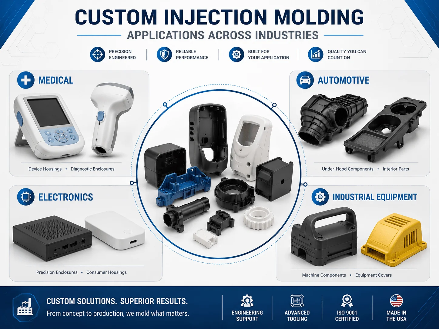
Injection molding remains the dominant manufacturing process for producing repeatable plastic parts at scale. It can deliver tight dimensional consistency, high-quality surfaces, integrated features, and competitive unit costs across thousands or millions of components. The challenge appears earlier in the product lifecycle: during NPI, a steel mold may require a substantial upfront investment before the design, material, and market demand are fully validated.
For Senior Mechanical Engineers, Product Designers, NPI Managers, and Purchasing Managers, the safest path is not to avoid injection molding but to stage the investment. A disciplined program combines material selection, DFM, prototype testing, rapid tooling, first-article approval, and supplier qualification. This guide explains how to reduce tooling risk, prevent common molding defects, estimate low-volume costs, and transition from functional prototypes to stable production.
How Injection Molding Works
Injection molding melts plastic pellets and injects the material into a closed mold under pressure. After the polymer fills the cavity, it cools and solidifies. The mold opens, ejector pins release the part, and the cycle begins again.
Part quality depends on geometry, polymer behavior, mold design, temperature, pressure, cooling time, venting, and ejection.
| Process Stage | Main Objective | Common Risk |
| Material drying | Remove moisture before molding | Splay, bubbles, degraded resin |
| Plasticizing | Melt and mix the polymer | Uneven temperature or contamination |
| Injection | Fill the cavity rapidly | Short shots, burn marks, trapped air |
| Packing | Compensate for material shrinkage | Sink marks or excess stress |
| Cooling | Stabilize part geometry | Warpage or long cycle time |
| Ejection | Remove the molded part | Drag marks, cracks, deformation |
The economic advantage comes from repetition. Once a reliable mold and process are established, each cycle can produce one or multiple parts with limited manual labor.
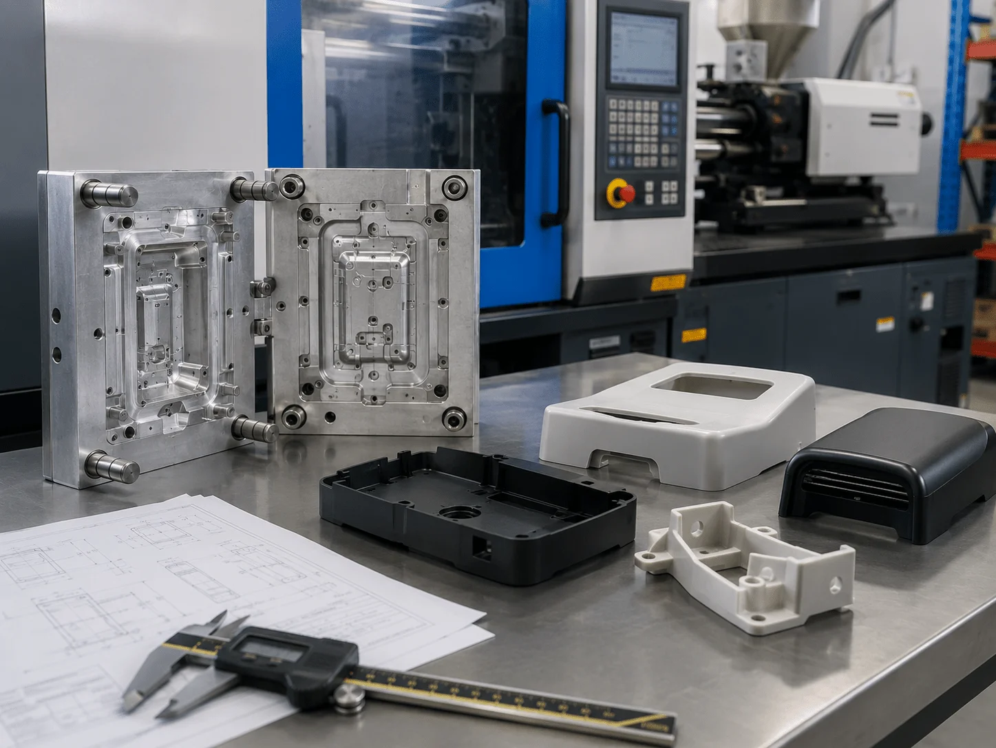
Industry Applications and Material Selection
Selecting the best plastic materials for injection molding
Selecting the best plastic materials for injection molding requires balancing performance, processing behavior, compliance needs, appearance, and total cost. No single polymer is ideal for every enclosure, clip, gear, medical component, or automotive part.
ABS is widely used for consumer electronics, smart hardware, and equipment housings because it molds well, accepts paint and texture, and provides a practical balance of stiffness, toughness, and cost. Polycarbonate offers higher impact resistance and heat performance, while PC/ABS blends combine the processability of ABS with improved toughness.
Polypropylene is lightweight, chemically resistant, and well suited to living hinges, containers, laboratory components, and selected medical-device parts. Nylon provides strength, fatigue resistance, and wear performance for automotive clips, gears, brackets, and mechanical components, although moisture absorption and dimensional change must be considered.
POM is useful for low-friction mechanisms and precision moving parts. PEEK can serve demanding high-temperature or chemically aggressive applications, but its material and processing costs are much higher.
| Material | Main Advantages | Typical Applications | Key Design Concern |
| ABS | Good appearance and processability | Housings, covers, controls | Moderate heat resistance |
| PC | High impact and transparency options | Guards, lenses, durable housings | Higher processing temperature |
| PC/ABS | Toughness plus good surface quality | Electronics and automotive interiors | Grade-specific shrinkage |
| PP | Chemical resistance and living hinges | Medical, packaging, fluid components | Higher molding shrinkage |
| Nylon | Strength, wear, fatigue resistance | Gears, clips, automotive parts | Moisture absorption |
| POM | Low friction and dimensional stability | Bearings, mechanisms, latches | Sensitive to processing temperature |
| PEEK | Heat and chemical resistance | Medical, aerospace, industrial parts | High material and tooling demands |
For medical applications, engineers must verify the exact grade, supplier documentation, contact conditions, sterilization method, and regulatory pathway. Automotive projects may prioritize heat aging, chemical resistance, UV exposure, flame behavior, or low-temperature impact, while consumer products often emphasize color, texture, gloss, and scratch resistance.
Material selection should be completed before final mold design because shrinkage, gate design, draft, cooling, and processing temperature vary by polymer.
Multi-Material Integration: insert molding vs overmolding differences
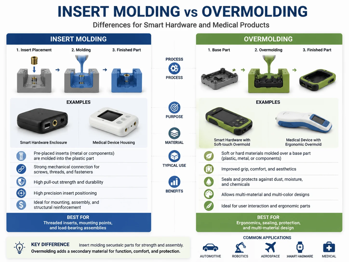
Understanding insert molding vs overmolding differences helps hardware and product teams integrate metal, rigid plastic, and soft-touch materials without unnecessary assembly operations.
Insert molding places a pre-manufactured component—such as a threaded brass insert, electrical terminal, magnet, pin, or metal frame—inside the mold. Plastic is injected around the insert, creating a mechanically integrated part. It is commonly used for threaded attachment points, electrical connectors, sensor components, and reinforced structures.
Overmolding adds a second polymer over a previously molded substrate. A rigid housing may receive a TPE grip, sealing edge, button surface, shock absorber, or decorative layer. It is widely used in medical handpieces, power tools, wearables, and consumer electronics.
| Factor | Insert Molding | Overmolding |
| Added element | Metal or pre-made component | Second plastic or elastomer |
| Main benefit | Strong integrated attachment | Grip, sealing, comfort, impact protection |
| Typical risk | Insert movement or poor encapsulation | Weak material adhesion or distortion |
| Tooling need | Insert-loading and retention features | One or two molds, depending on process |
| Common use | Threads, terminals, magnets | TPE grips, seals, soft buttons |
For insert molding, the insert must be held securely against injection pressure. Knurls, grooves, undercuts, and through-holes improve mechanical retention.
For overmolding, chemical compatibility between the substrate and overmold is critical. Mechanical interlocks can provide additional security when adhesion alone is insufficient.
Engineers should also account for thermal expansion. A large metal insert may cool differently from the surrounding plastic and create stress, sink, or warpage. Prototype testing should use production-intent materials whenever possible.
Prototyping and Low-Volume Tooling Options
Bridging the Gap with rapid tooling for injection molding prototypes
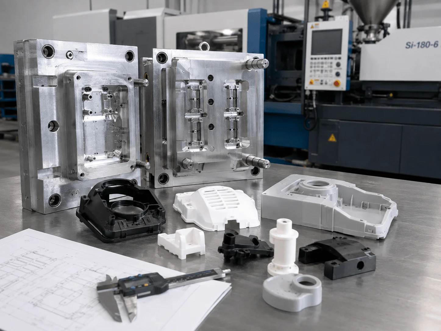
Rapid tooling for injection molding prototypes allows an NPI team to produce parts from real injection-molding materials before committing to a long-life production mold. It is especially useful when 3D-printed parts cannot provide the required surface, material behavior, assembly strength, or repeatability.
Rapid molds may use aluminum, pre-hardened steel, modular mold bases, manual inserts, simplified cooling, or reduced automation. They are commonly used to manufacture approximately 100 to several thousand parts for engineering validation, certification preparation, pilot builds, field trials, or bridge production.
A staged development route may look like this:
| Development Stage | Recommended Method | Primary Goal |
| Concept review | SLA, SLS, or FDM | Confirm shape, ergonomics, and assembly concept |
| Functional prototype | CNC machining or urethane casting | Test material-like behavior and fit |
| Process validation | Rapid injection tooling | Produce molded parts in production-intent resin |
| Pilot production | Improved rapid or bridge tooling | Validate quality and assembly workflow |
| Volume production | Hardened steel tooling | Achieve long mold life and low unit cost |
Rapid tooling reduces financial exposure, but it should not be treated as disposable machining without engineering. Gate location, parting line, draft, venting, shrinkage, ejection, and cooling still determine whether the part can be molded consistently.
The strongest business case appears when molded prototypes must validate snap fits, living hinges, transparent grades, threaded inserts, sealing features, or production-intent material performance.
Lowering Upfront Costs with prototype injection tooling aluminum molds
Prototype injection tooling aluminum molds can shorten lead time and reduce initial tool cost because aluminum is easier to machine and transfers heat efficiently. It is suitable for prototypes, market-validation batches, low-volume production, and designs that may still change.
Compared with hardened steel, aluminum is softer and less wear-resistant. It is not the right choice for every abrasive, glass-filled, high-temperature, or very high-volume application. However, for many unfilled thermoplastics and moderate quantities, it provides an effective route to production-quality molded parts.
| Tooling Factor | Aluminum Mold | Hardened Steel Mold |
| Initial investment | Lower | Higher |
| Toolmaking lead time | Shorter | Longer |
| Heat transfer | Excellent | Good, design-dependent |
| Expected mold life | Lower | Much higher |
| Design-change flexibility | Easier in early stages | More costly after hardening |
| Best application | Prototype and low volume | Stable high-volume production |
Standard mold bases, interchangeable cavity inserts, manual side actions, and hand-loaded components can reduce upfront investment when quantities are limited.
These solutions trade automation for lower tooling cost. A hand-loaded core may be acceptable for 500 pilot parts but inefficient for 100,000 production components.
The toolmaker should still protect critical shutoffs, thin steel conditions, sealing areas, and high-wear features. Steel inserts may be added locally where an all-aluminum surface would wear too quickly.
Design for Manufacturability
Defect Prevention: plastic injection molding defects and remedies
A practical review of plastic injection molding defects and remedies should begin in CAD. Process settings cannot fully compensate for poor wall transitions, trapped air, weak flow paths, or difficult ejection.
Sink Marks
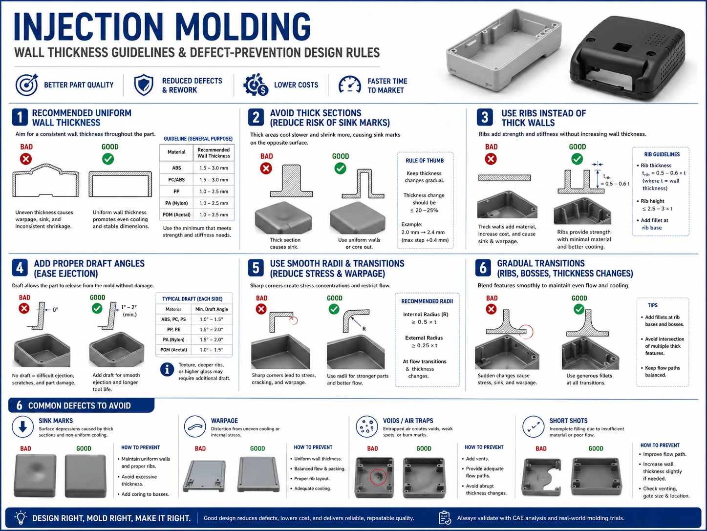
Sink marks appear as depressions above thick ribs, bosses, or other material concentrations. The interior cools and shrinks after the outer skin has solidified.
Potential remedies include:
Coring out thick areas
Reducing rib and boss thickness
Maintaining more uniform walls
Improving packing pressure
Positioning gates so material can feed the region during cooling
A mounting boss should generally be hollow and supported by ribs rather than designed as a solid cylinder attached to a thin wall.
Warpage
Warpage occurs when different regions shrink at different rates. Causes include uneven wall thickness, unbalanced ribs, asymmetric geometry, poor cooling, molecular orientation, and unsuitable gate placement.
Designers can reduce warpage by balancing the geometry, using uniform walls, adding controlled ribs, avoiding large unsupported flat panels, and aligning the design with predictable material flow.
Large panels may benefit from shallow curvature, structured ribs, or perimeter reinforcement rather than simply increasing the wall thickness.
Weld Lines
Weld lines form where separate flow fronts meet around holes, inserts, or multiple gates. They may create a visible line or a mechanically weaker region.
Possible remedies include relocating the gate, adjusting wall geometry, changing the flow path, improving venting, or moving the weld line away from a highly loaded or cosmetic surface.
For a sealed housing, a weld line should not be positioned across a critical gasket surface without careful validation.
Short Shots
A short shot occurs when the cavity does not fill completely. Thin sections, long flow lengths, poor venting, low material temperature, insufficient pressure, or restricted gates may contribute.
Increasing wall thickness locally, reducing unnecessary flow distance, improving vents, and selecting a resin with suitable flow properties can help.
Flash
Flash is excess material along the parting line, ejector, slide, or insert interface. It may result from tool wear, poor mold fit, excessive pressure, inadequate clamping, or an unsupported shutoff.
The design should avoid delicate shutoffs and extremely thin tool-steel sections. The mold should also be built and maintained to preserve proper alignment.
Burn Marks and Trapped Gas
Burn marks often result from trapped air or degraded material. Better venting and improved flow control may reduce the problem.
Vents are commonly placed near the end of the filling path, around deep ribs, and in regions where air could otherwise become trapped.
| Defect | Likely Design Contributor | DFM Remedy |
| Sink marks | Thick boss or rib intersection | Core the feature and reduce local mass |
| Warpage | Uneven walls or unbalanced ribs | Balance geometry and cooling behavior |
| Weld lines | Split flow around openings | Relocate gate or move the critical feature |
| Short shot | Thin wall and long flow path | Improve flow capability or revise geometry |
| Flash | Weak shutoff or poor parting design | Strengthen tool geometry and sealing surfaces |
| Burn mark | Trapped air | Add or improve venting |
The Golden Rule: injection molding wall thickness guidelines
Reliable injection molding wall thickness guidelines begin with one principle: keep the nominal wall as uniform as the product function allows. Uniform walls fill and cool more predictably, reducing sink, internal stress, cycle time, and warpage.
The following ranges are practical starting points rather than universal specifications:
| Material | Typical Starting Wall Range |
| ABS | 1.2–3.5 mm |
| Polycarbonate | 1.0–3.5 mm |
| PC/ABS | 1.2–3.5 mm |
| Polypropylene | 0.8–3.0 mm |
| Nylon | 0.8–3.0 mm |
| POM | 0.8–3.0 mm |
| PEEK | 1.0–3.0 mm |
Actual limits depend on flow length, material grade, fillers, gate design, surface requirements, and machine capability.
When a thickness change is unavoidable, use a gradual transition rather than an abrupt step. A tapered transition reduces flow hesitation and differential shrinkage.
Ribs should add stiffness without becoming hidden thick sections. A common starting point is to make rib thickness a fraction of the adjoining wall. The exact ratio should be reviewed according to the resin, cosmetic requirements, and rib location.
Bosses should be cored and supported by ribs rather than attached as solid cylinders. Isolating a boss slightly from an exterior cosmetic wall can also reduce visible sink marks.
Draft is essential. Vertical walls need sufficient draft to release without drag marks or ejection stress. Texture normally requires additional draft because the surface pattern mechanically engages with the mold.
Internal features often need more careful review because they shrink onto the mold core. Deep internal walls, textured cores, and tall ribs may require increased draft.
Sourcing and Cost Optimization
Cost Breakdown: low volume injection molding cost Drivers
The low volume injection molding cost has two major components: non-recurring tooling investment and recurring part cost. The correct sourcing decision depends on total program cost, not the lowest mold quote or unit price considered separately.
Tooling cost is influenced by:
Part size and cavity count
Mold material
Slides, lifters, and unscrewing actions
Surface texture and polishing
Cooling complexity
Insert-molding requirements
Tolerance and inspection needs
Expected mold life
Part cost is influenced by resin, shot weight, cycle time, scrap rate, machine size, labor, secondary operations, quality control, packaging, and order quantity.
| Quantity | Typical Approach | Financial Priority |
| 1–20 | 3D printing, CNC, or casting | Avoid tooling |
| 20–100 | Compare casting with rapid molding | Validate design and market need |
| 100–1,000 | Aluminum rapid tooling | Balance tool cost and part fidelity |
| 1,000–10,000 | Bridge or production tooling | Reduce unit cost and stabilize supply |
| 10,000+ | Production steel mold | Tool life, automation, cycle time |
For 500 validation parts, manual inserts or hand-loaded cores may cost less than automated side actions, although they increase labor and cycle time.
Family molds can also reduce initial investment by placing several related parts in one tool. However, different part sizes and flow requirements may complicate filling, balancing, and process control.
Engineers can lower cost by:
Eliminating unnecessary undercuts
Using standard mold textures
Minimizing cosmetic requirements on hidden surfaces
Selecting standard resin colors
Simplifying assembly
Reducing unnecessary tool actions
Applying tight tolerances only where functionally necessary
Designing several related parts around common materials and finishes
A transparent quotation should separate mold cost, unit cost, resin, inserts, finishing, inspection, packaging, and shipping. This allows procurement teams to compare suppliers on the same basis.
Scaling Production with custom plastic injection molding services
Selecting custom plastic injection molding services requires evaluating whether the supplier can support the complete product lifecycle.
A strong partner should be capable of producing rapid aluminum tooling for validation and hardened steel tooling for stable volume production, either directly or through a tightly controlled supply chain.
Key capabilities include:
DFM and mold-flow analysis
Material selection support
Prototype and rapid tooling
Production mold design and manufacturing
Insert molding and overmolding
Process development and validation
Dimensional inspection
Surface finishing and decoration
Assembly and packaging
Tool maintenance and revision control
A complete RFQ should include CAD files, drawings, material grade, color, finish, quantity, annual forecast, critical tolerances, inserts, cosmetic standards, and validation requirements.
Suppliers should explain gate location, parting line, ejector marks, draft concerns, likely weld lines, and anticipated shrinkage before tool cutting begins. This review demonstrates engineering involvement and helps prevent disputes after sampling.
The supplier should also explain how engineering changes will be managed. A small change to a rib or opening may be relatively simple, while moving a critical shutoff, slide, or cooling feature can require significant tool rework.
Injection Molding Application Scenarios
Medical Device Enclosure
A medical technology company needs 500 sealed housings for verification. Rapid aluminum tooling can produce parts in production-intent material while the engineering team tests gaskets, connectors, cleaning resistance, fastening, and assembly.
The team must still verify the exact resin grade and documentation required for the intended use.
Consumer Electronics Housing
A hardware startup requires 1,500 premium enclosures for a pilot launch. Injection molding can deliver consistent texture, color, snap fits, bosses, and thin walls that would require substantial finishing with many additive processes.
Rapid tooling also allows the company to test market demand before committing to a high-volume multi-cavity mold.
Automotive Connector
An automotive supplier needs a glass-filled nylon connector with metal terminals. Insert molding integrates the terminals, reduces assembly, and supports repeatable positioning.
The mold must prevent terminal movement, control flash around the metal interface, and maintain the required electrical and sealing geometry.
Robotics Handheld Controller
A robotics company needs a rigid controller housing with a soft TPE grip. Overmolding can improve comfort, impact resistance, and visual differentiation while reducing separate assembly operations.
Material compatibility and mechanical locking features should be tested before production tooling is approved.
Industrial Sensor Housing
An automation manufacturer requires a chemical-resistant housing with threaded inserts and a gasket interface. Production-intent molded parts allow the team to validate insert retention, flatness, connector fit, sealing dimensions, and installation torque.
Frequently Asked Questions
What is rapid injection molding?
Rapid injection molding uses simplified or faster-to-manufacture tooling to produce molded parts in production-intent thermoplastics. It is commonly used for engineering validation, bridge production, pilot launches, and lower-volume orders.
When should I choose aluminum tooling?
Aluminum tooling is appropriate when lead time and upfront investment are more important than maximum mold life. It is often used for prototypes and low-volume production with non-abrasive materials.
Highly abrasive, glass-filled, or very high-temperature resins may require steel inserts or a steel mold.
What causes sink marks in injection-molded parts?
Sink marks are commonly caused by thick material concentrations, oversized ribs or bosses, inadequate packing, and uneven cooling.
Coring thick areas, reducing rib thickness, improving wall uniformity, and positioning the gate to support effective packing can reduce the risk.
How can warpage be reduced?
Use balanced geometry, uniform walls, practical ribs, suitable gate placement, controlled cooling, and a polymer grade appropriate for the design.
Mold-flow analysis can help identify uneven filling, pressure, cooling, and shrinkage before the mold is manufactured.
What wall thickness is best for injection molding?
The best wall thickness depends on the resin, flow length, part size, structural requirements, and cosmetic expectations.
Uniformity is usually more important than selecting the thinnest possible wall. Changes in thickness should be gradual.
Is insert molding stronger than installing inserts later?
Insert molding can provide strong integration and eliminate a secondary assembly operation. Final strength depends on insert geometry, plastic material, wall design, surface preparation, and processing conditions.
Post-installed heat-set or ultrasonic inserts may still be more practical for some low-volume projects.
What is the difference between overmolding and two-shot molding?
Overmolding broadly describes molding one material over another substrate. Two-shot molding uses a specialized machine and mold to produce two materials in an automated cycle.
Low-volume overmolding may use separately molded substrates that are manually loaded into a second tool.
How much does low-volume injection molding cost?
Cost depends on part size, material, mold design, tool actions, finish, quantity, inspection, and production location.
The total should be evaluated as tooling investment plus recurring unit cost across the expected order volume.
What files are needed for an injection molding quote?
Provide STEP or native CAD data, 2D drawings, material, color, finish, quantities, annual forecast, tolerances, inserts, cosmetic requirements, and intended application.
Information about expected future production volume helps the supplier recommend the correct tooling strategy.
Can a rapid mold be upgraded for mass production?
Sometimes, but not always. A rapid tool may use different materials, cooling systems, actions, and mold-base assumptions from a production tool.
The supplier should confirm before manufacturing whether cavity inserts, cores, or other components can be reused later.
Injection molding becomes less risky when tooling is treated as a staged engineering investment. Select the resin around real application needs, validate critical functions, use rapid tooling for production-intent parts, and complete DFM before releasing a long-life mold.
Uniform walls, practical draft, well-designed ribs and bosses, controlled undercuts, and clear tolerance priorities prevent many expensive molding problems. Procurement teams can then compare total program cost and select a partner capable of supporting both low-volume validation and future scale.
Accelerate Your Injection Molding Project with GC-Prototype
Securing a market launch requires high-fidelity parts without draining your R&D budget on high-volume hard tooling. Whether you are a Senior Mechanical Engineer designing sealed medical device enclosures or a Sourcing Manager seeking high-quality, low-volume custom plastic injection molding, GC-Prototype is ready to accelerate your timeline.
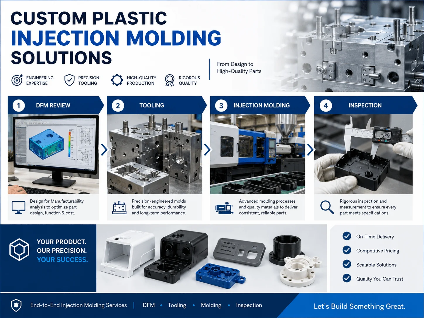
Our capabilities include DFM review, rapid aluminum tooling, production steel molds, insert molding, overmolding, precision injection molding, inspection, finishing, assembly, and low-volume manufacturing.