Address:
Shenzhen Bao'an District Xinqiao Subdistrict Huangpu Community Huangpu East Ring Road No. 504 Shenzhen Yuan Industrial City Building C
Work Hours:
Monday to Friday: 9AM - 21PM
Weekend: 9AM - 21PM

Address:
Shenzhen Bao'an District Xinqiao Subdistrict Huangpu Community Huangpu East Ring Road No. 504 Shenzhen Yuan Industrial City Building C
Work Hours:
Monday to Friday: 9AM - 21PM
Weekend: 9AM - 21PM

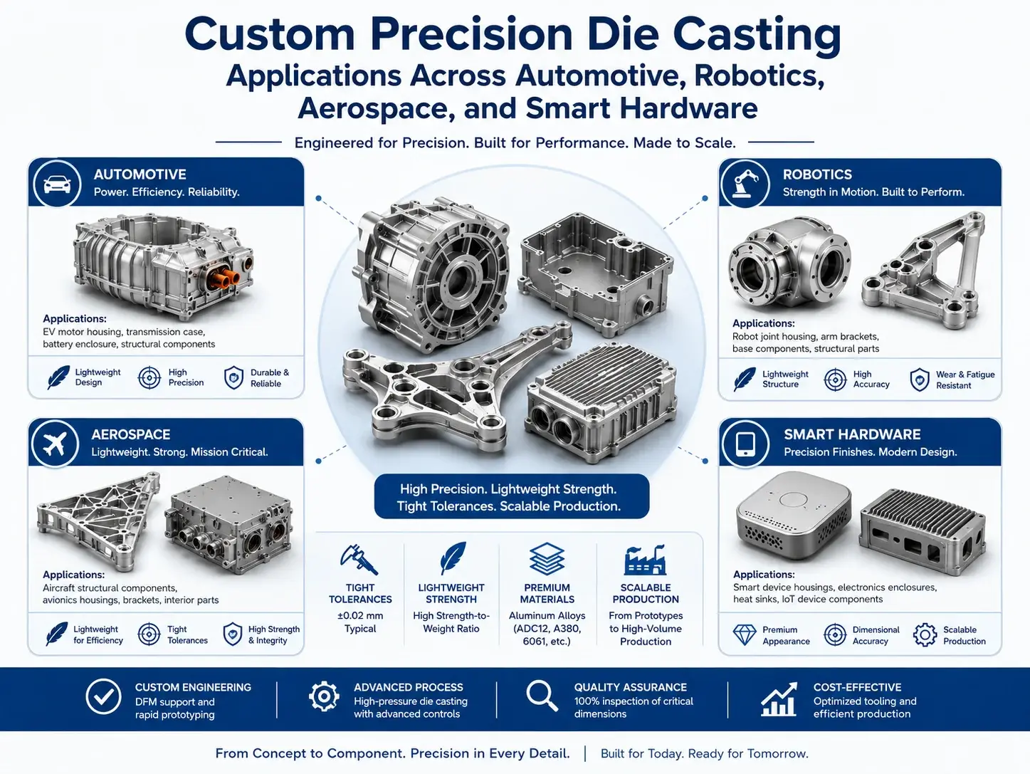
Pressure die casting is one of the most effective manufacturing processes for producing thin-walled, high-strength metal parts with complex geometry, repeatable dimensions, and production-ready surface quality. It is widely used for automotive structures, electronics housings, industrial equipment, robotics components, aerospace hardware, and medical device enclosures.
The challenge is the upfront investment. Production dies can be expensive, and design changes after tooling approval may lead to major delays and rework costs. Senior Mechanical Engineers, NPI Managers, and Sourcing Managers therefore need a clear strategy for validating geometry, selecting alloys, managing tooling risk, and preventing casting defects before mass production begins.
This guide explains material selection, prototype strategies, rapid tooling, wall-thickness rules, defect prevention, surface quality, cost drivers, supplier qualification, and the transition from engineering samples to repeat production.
How Pressure Die Casting Works
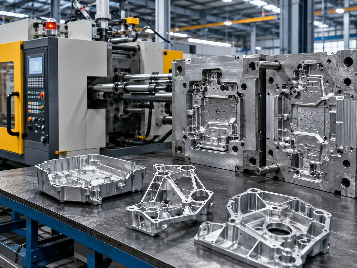
Pressure die casting injects molten metal into a hardened steel mold at high speed and pressure. The metal fills the cavity, reproduces detailed features, and solidifies quickly. The die opens, ejector pins release the casting, and excess material is removed.
A typical manufacturing sequence includes:
1.Alloy melting and temperature control
2.Die lubrication and preparation
3.High-speed cavity filling
4.Intensification pressure
5.Cooling and solidification
6.Part ejection
7.Runner and overflow trimming
8.Shot blasting or deburring
9.CNC post-machining
10.Surface finishing and inspection
The process can produce ribs, bosses, mounting features, heat-dissipation structures, text, logos, and thin walls in one casting. This reduces assembly work and may consolidate several machined or fabricated components into a single part.
However, tooling and process development are critical. Gate location, venting, overflow design, wall transitions, cooling, draft, alloy selection, and machine capacity all affect quality.
| Process characteristic | Pressure die casting benefit | Engineering consideration |
| High-pressure filling | Thin walls and detailed features | Poor flow design can trap air |
| Steel production tooling | High repeatability | Significant upfront investment |
| Rapid solidification | Short production cycles | Thick sections may create shrinkage |
| Integrated geometry | Fewer assembled components | Tooling must allow ejection |
| Good as-cast finish | Less secondary finishing | Gate and parting marks remain |
| High-volume capability | Competitive unit cost | Not always economical for unstable designs |
Industry Applications and Material Selection
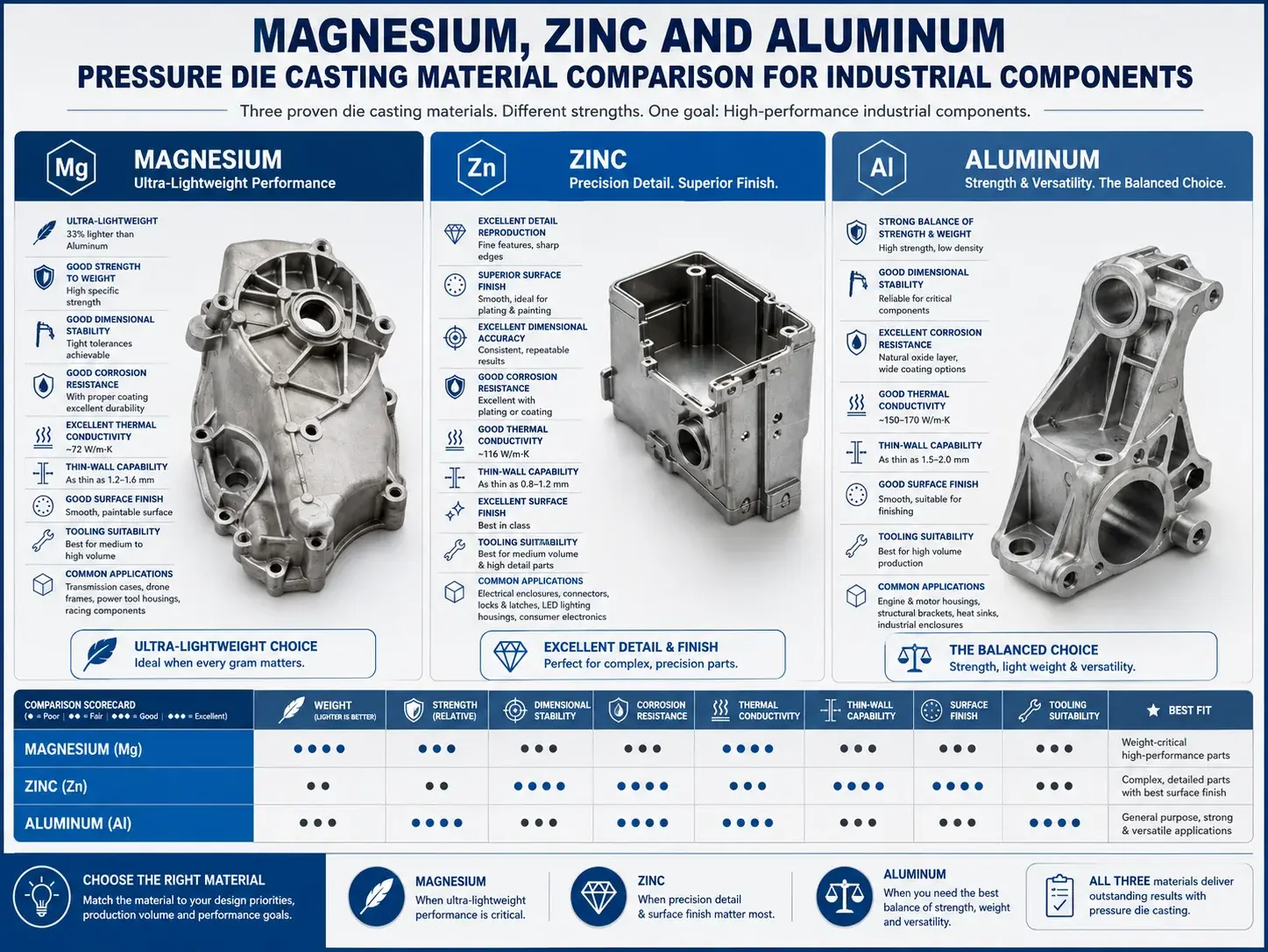
Different die-casting alloys provide different combinations of density, strength, corrosion resistance, thermal behavior, dimensional stability, and casting performance. Selecting the alloy only by raw-material price can produce misleading cost decisions.
The complete evaluation should include tooling life, cycle time, machining, finishing, weight, reject rate, mechanical requirements, and expected annual demand.
Lightweight Efficiency: magnesium die casting for automotive parts
Magnesium die casting for automotive parts is valuable when weight reduction, vibration control, and complex structural integration are important. Magnesium is significantly lighter than aluminum and steel, making it attractive for vehicles, drones, robotics systems, portable equipment, and mobility products.
Typical magnesium die-cast applications include:
Steering and instrument components
Seat and interior structures
Transmission covers
Electronic control housings
Camera and sensor frames
Drone structures
Robotic arm components
Lightweight brackets
Portable equipment housings
Magnesium alloys can fill thin and complex cavities effectively, supporting lightweight designs with ribs, bosses, and integrated mounting features. Their damping behavior can also help reduce vibration in selected mechanical and electronic assemblies.
The material is not automatically the best option for every lightweight product. Engineers must evaluate corrosion protection, surface finishing, flammability controls during manufacturing, mechanical loading, joining methods, and long-term environmental exposure.
A magnesium casting may require conversion coating, painting, powder coating, plating, or another protective finish. Fastener interfaces and contact with dissimilar metals should also be reviewed to reduce galvanic corrosion risk.
For automotive and robotics prototypes, a CNC-machined magnesium or aluminum component can validate geometry and assembly, but it will not fully reproduce pressure-cast flow, porosity, grain structure, or thin-wall behavior. When those characteristics matter, rapid die-casting tooling or a controlled casting trial becomes necessary.
Materials and Economics: zinc die casting vs aluminum die casting cost
The zinc die casting vs aluminum die casting cost comparison involves more than the price per kilogram. Zinc and aluminum differ in melting temperature, density, machine requirements, tool life, wall capability, cycle time, mechanical properties, and secondary finishing.
Zinc alloys fill small details exceptionally well. They are often selected for miniature precision components, decorative hardware, connector bodies, gears, latches, locks, and compact mechanisms. Zinc’s relatively low casting temperature can support long die life and efficient production.
Aluminum alloys provide lower density, strong overall mechanical performance, useful thermal conductivity, and broad industrial acceptance. They are widely used for automotive housings, electronics enclosures, heat sinks, structural components, pump bodies, and industrial equipment.
| Comparison factor | Zinc die casting | Aluminum die casting |
| Density | Higher | Lower |
| Typical part size | Small to medium | Medium to large |
| Thin-detail capability | Excellent | Very good |
| Tooling life | Often longer | Generally shorter than zinc tooling |
| Casting temperature | Lower | Higher |
| Mechanical performance | Strong and dimensionally stable | Good strength-to-weight balance |
| Thermal conductivity | Moderate | Strong |
| Common applications | Small precision and decorative parts | Structural, thermal, and lightweight housings |
| Raw-material cost impact | Depends on market and part weight | Depends on alloy and part volume |
| Total cost advantage | Small detailed parts and long runs | Lightweight parts and broader structures |
Zinc may be financially attractive for small components because it fills intricate features efficiently and can reduce secondary machining. However, its higher density increases finished-part weight.
Aluminum may cost more to tool and process in some applications, but it can reduce product weight and perform better in larger structural or thermal-management components.
Procurement teams should compare total landed cost rather than raw alloy price. The analysis should include:
Finished part weight
Tooling investment
Expected die life
Production cycle time
CNC post-machining
Surface treatment
Scrap and remelting
Quality inspection
Packaging and freight
Annual volume
Bridging the Gap: Prototyping and Rapid Tooling
Production die casting is economically powerful after the design and process are stable. Before that point, tooling creates risk. A minor change to a boss, rib, sealing surface, connector location, or draft angle may require expensive tool modification.
A staged prototype strategy helps separate basic design verification from process validation.
Risk Mitigation: aluminum pressure die casting prototyping Strategies
Effective aluminum pressure die casting prototyping begins by identifying what the prototype must prove.
A prototype may need to validate:
Overall geometry
Assembly clearances
Mechanical loading
Thread and insert locations
Sealing interfaces
Thermal performance
Weight and ergonomics
Surface appearance
Machining access
Actual casting behavior
No single prototype method answers every question.
CNC machining aluminum billet is usually the fastest way to test geometry, assembly, and selected mechanical performance. It uses real aluminum and can provide tight dimensions without casting tooling.
However, billet-machined aluminum does not reproduce die-cast porosity, draft, parting lines, ejection marks, flow behavior, local material structure, or as-cast wall limitations.
3D printing can produce complex shapes quickly and economically for design review, but polymer prints cannot represent the mechanical and thermal performance of aluminum. Metal additive manufacturing may provide metal parts, although its structure, finish, cost, and post-processing differ from die casting.
A practical validation plan may use several stages:
| Development stage | Recommended method | Main question answered |
| Early concept | Polymer 3D printing | Does the shape and assembly concept work? |
| Engineering prototype | CNC-machined aluminum | Do dimensions, interfaces, and loads work? |
| Casting feasibility review | Flow simulation and DFM | Can the geometry fill, cool, and eject reliably? |
| Process prototype | Rapid die-casting tooling | How does the real casting process perform? |
| Pilot production | Production-intent die and controls | Is the process ready for volume? |
CNC prototypes should be redesigned with production die casting in mind. Features that are simple to machine may be difficult to cast. Sharp internal corners, zero draft, thick masses, deep narrow pockets, and inaccessible slides can create tooling or quality problems.
The die-casting supplier should perform DFM before hard tooling begins. This review should cover part orientation, parting line, gate location, overflow, ejector positions, draft, wall thickness, machining allowances, and dimensional datums.
Accelerating NPI: rapid tooling for die casting prototypes
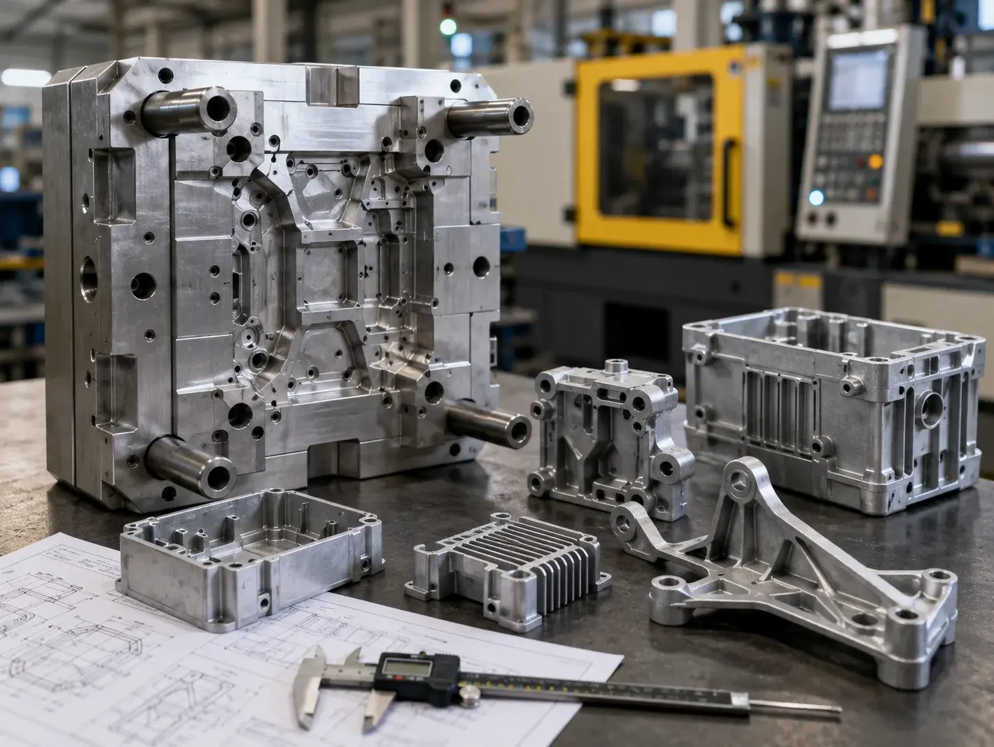
Rapid tooling for die casting prototypes enables teams to produce real cast components before investing in full production tooling. The approach may use simplified inserts, soft steel, pre-existing mold bases, reduced automation, or tools designed for limited quantities.
Rapid tooling is suitable when teams need 100–500 parts for:
Engineering validation
Vehicle or machine testing
Thermal testing
Customer qualification
Assembly-line trials
Certification preparation
Pilot-market builds
Process development
The exact quantity depends on part size, alloy, geometry, tooling material, machine conditions, and quality requirements.
Rapid tooling can reduce initial lead time by simplifying non-essential tooling features. It may use manual inserts or trimming where production tooling would use automated slides, dedicated trim dies, or complex cooling circuits.
| Tooling option | Upfront cost | Lead time | Typical purpose |
| No casting tool | Lowest | Shortest | Printed or CNC geometry validation |
| Simplified rapid tool | Moderate | Several weeks | Real cast samples and pilot batches |
| Bridge-production tool | Higher | Medium | Low-volume repeat production |
| Full production tool | Highest | Longest | Stable high-volume manufacturing |
Rapid tooling does not remove the need for engineering. The tool must still survive injection pressure and thermal cycling. Gates, vents, overflows, cooling, ejection, and parting surfaces must be designed correctly.
The cost case is strongest when real casting performance must be tested before the final die is released. Identifying porosity, distortion, fill imbalance, machining issues, or assembly variation during a rapid-tooling run can prevent far more expensive production failures.
Pressure Die Casting Cost Analysis
The cost of a die-cast program includes both non-recurring engineering and recurring production expenses.
Non-Recurring Costs
DFM and process engineering
Mold-flow analysis
Tool design
Tool steel and machining
Slides and inserts
Cooling system
Ejection system
Trim tooling
Fixtures
Gauges
Sampling and validation
Recurring Costs
Alloy
Machine cycle time
Melting energy
Tool lubrication
Trimming
Deburring
CNC post-machining
Surface treatment
Inspection
Packaging
Freight
A simplified cost model can be expressed as:
Total program cost = tooling and engineering + unit production cost × quantity
As volume increases, the tooling investment is spread over more components. This is why die casting becomes highly competitive for stable, repeatable designs.
| Production volume | Likely strategy | Main cost concern |
| 1–20 parts | CNC machining or additive prototype | Prototype unit price |
| 20–100 parts | CNC or specialized prototype casting | Design flexibility |
| 100–500 parts | Rapid tooling may be justified | Tooling versus validation value |
| 500–5,000 parts | Bridge or production tooling review | Break-even point |
| High repeat volume | Full production tooling | Cycle time, yield, tool maintenance |
The break-even point varies widely. A small zinc part may justify tooling at a different volume than a large aluminum housing with slides and extensive machining.
Sourcing teams should request a transparent quotation that separates tooling, casting, trimming, machining, finishing, inspection, and packaging. This makes it easier to identify cost-reduction opportunities.
Design for Manufacturability
The casting process must be considered while the part is still in CAD. Design decisions directly affect cavity filling, air escape, solidification, ejection, machining, tool complexity, and rejection rates.
Minimizing Rejects: designing for pressure die casting defects
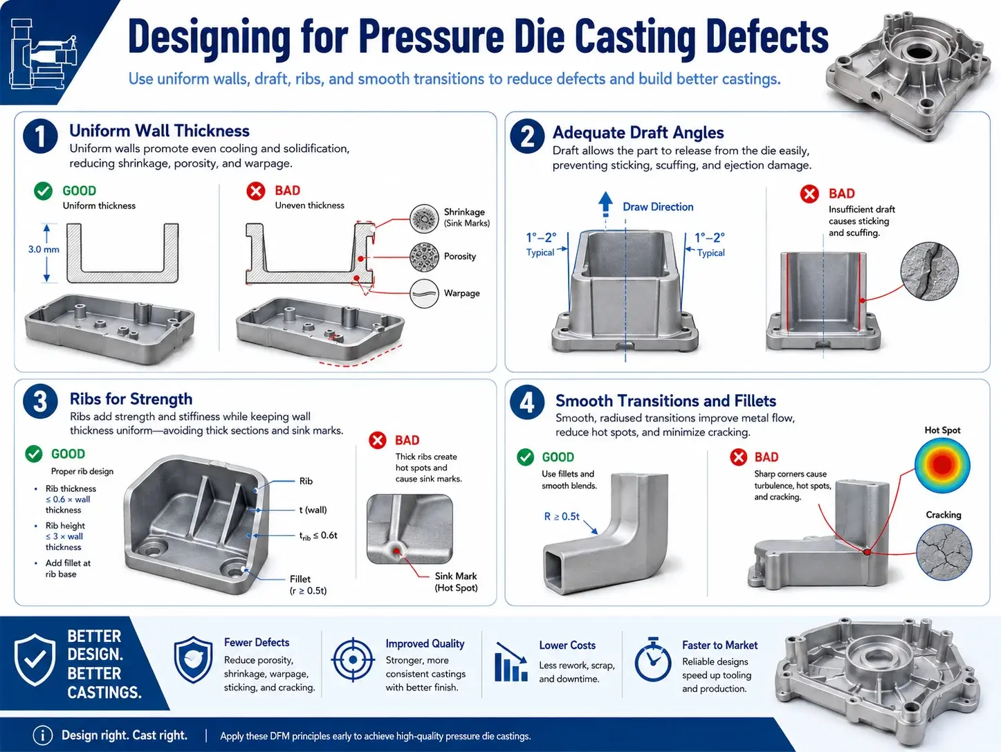
Designing for pressure die casting defects means creating geometry that supports smooth metal flow, controlled solidification, air evacuation, and reliable ejection.
Common defects include porosity, cold shuts, incomplete fill, shrinkage cavities, flow marks, blistering, warpage, cracking, and flash.
Porosity
Gas porosity can form when air is trapped during high-speed filling. Shrinkage porosity can form when thick regions solidify unevenly and cannot receive sufficient feed metal.
Porosity may remain harmless inside a cosmetic housing but become unacceptable near machined sealing surfaces, threaded holes, structural areas, or pressure-containing features.
Design strategies include:
Maintaining relatively uniform walls
Reducing isolated thick masses
Using ribs instead of solid blocks
Positioning machined surfaces carefully
Supporting effective gate and overflow design
Avoiding unnecessary local heat concentration
Cold Shuts and Incomplete Filling
Cold shuts occur when separate metal-flow fronts meet without fusing properly. Incomplete filling occurs when metal solidifies before fully filling a region.
Risk increases with thin, long flow paths, abrupt wall transitions, poor venting, low metal temperature, or unsuitable gating.
Engineers can reduce risk by using smooth transitions, realistic wall thicknesses, practical flow distances, and radiused corners.
Shrinkage
Thick bosses, pads, and intersections cool more slowly than surrounding walls. This may create internal voids or surface depressions.
Instead of making a mounting boss fully solid, core it and connect it with ribs. Keep adjoining wall sections balanced where possible.
Warpage
Warpage may result from uneven wall thickness, unbalanced ribs, asymmetric geometry, uneven cooling, or ejection stress.
Large flat surfaces should be supported using shallow ribs, curvature, or structured features rather than excessive thickness.
Draft and Ejection
Draft allows the casting to release from the die. Vertical walls with insufficient draft can drag against the tool, damage the surface, or create ejection distortion.
Required draft depends on alloy, depth, texture, wall orientation, and tool design. Textured surfaces generally require more draft than smooth surfaces.
Fillets and Corners
Sharp corners restrict flow and concentrate stress. Fillets improve filling, reduce local stress, and support longer tool life.
DFM should be completed jointly by the product designer, die designer, process engineer, and post-machining team.
Engineering Standards: die casting minimum wall thickness guidelines
Practical die casting minimum wall thickness guidelines depend on alloy, part area, flow length, machine size, geometry, rib structure, and casting conditions.
The following values are useful starting references rather than universal guarantees:
| Alloy family | Practical starting range for small or medium parts | Key consideration |
| Zinc alloys | Approximately 0.5–1.0 mm | Strong thin-detail capability |
| Magnesium alloys | Approximately 0.8–1.2 mm | Lightweight and good fill behavior |
| Aluminum alloys | Approximately 1.0–1.5 mm | Widely used for structural housings |
| Larger castings | Often require thicker nominal walls | Longer flow path and structural needs |
A wall that is too thin may fail to fill consistently. A wall that is unnecessarily thick increases metal use, cycle time, weight, and shrinkage risk.
Uniformity is often more important than selecting the absolute minimum thickness. Abrupt transitions from 1 mm to a large solid boss create greater risk than a consistently designed 1.5 mm structure.
Useful DFM principles include:
Keep primary walls consistent.
Core thick bosses.
Connect bosses with ribs.
Use gradual wall transitions.
Avoid heavy intersections.
Add draft to formed surfaces.
Use fillets at internal corners.
Review flow length relative to thickness.
Provide machining stock only where required.
Coordinate ribs with ejector and gate design.
Ribs should support stiffness without creating isolated thick sections. A rib that is excessively thick relative to the adjoining wall may create sink, shrinkage, or local hot spots.
Threaded features often require drilled and tapped holes, inserts, or secondary machining. Cast threads are possible in selected designs but may increase tool complexity and are not appropriate for every application.
Aesthetics and Sourcing Strategy
Quality Comparison: die casting vs sand casting surface finish
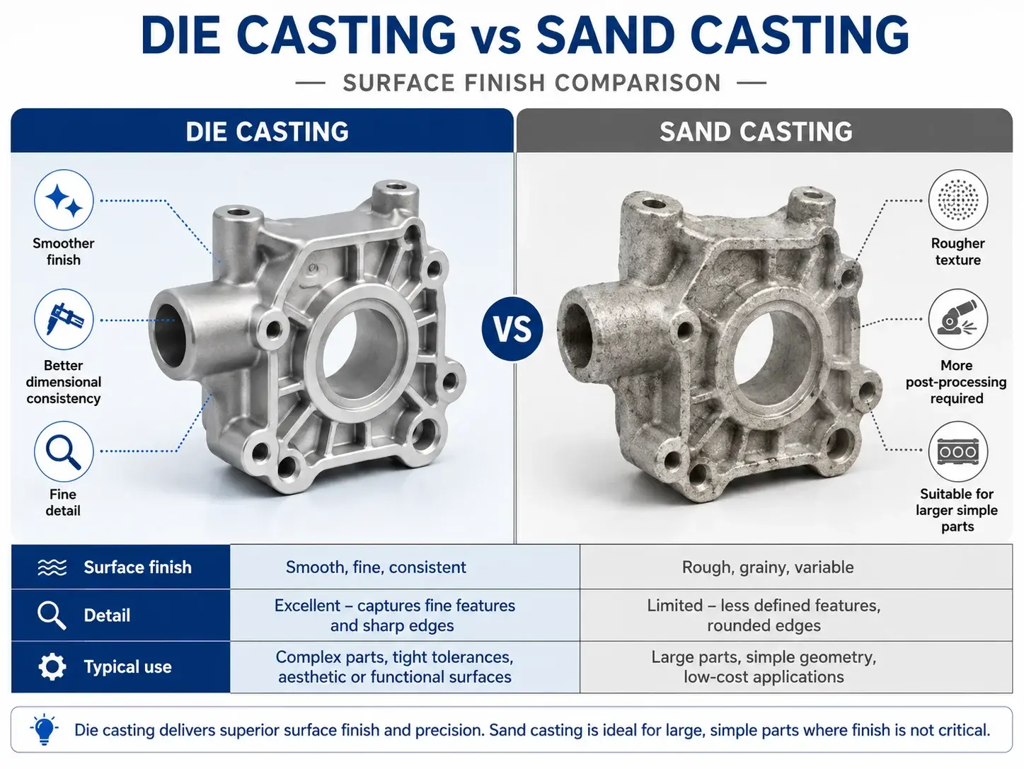
The die casting vs sand casting surface finish comparison strongly favors pressure die casting when a component requires smooth surfaces, fine detail, thin walls, and repeatable geometry.
Sand casting forms a cavity in bonded sand. It is flexible and suitable for large parts, low quantities, and alloys that may not be processed through pressure die casting. However, the sand texture transfers to the casting and normally creates a rougher surface.
Pressure die casting uses a machined steel cavity, allowing the part to reproduce finer geometry and smoother surfaces.
| Quality factor | Pressure die casting | Sand casting |
| Surface finish | Smooth and detailed | Rougher sand texture |
| Wall capability | Thin walls possible | Usually thicker |
| Dimensional repeatability | High | Moderate |
| Small feature definition | Strong | More limited |
| Tooling investment | High | Lower |
| Production speed | Fast at volume | Slower |
| Part size | Small to medium, sometimes large | Strong option for large castings |
| Ideal volume | Medium to high | Prototype to lower volume |
Pressure die casting can reduce secondary machining because mounting features, ribs, openings, logos, and external geometry may be formed directly in the tool.
Machining is still required for critical bores, sealing surfaces, tight threaded holes, bearing fits, and precision interfaces.
Surface requirements should be defined before tooling. Cosmetic standards may influence gate placement, parting lines, ejector locations, trimming, polishing, blasting, and coating.
Common finishing options include:
Shot blasting
Vibratory finishing
Polishing
Powder coating
Wet painting
Anodizing for suitable aluminum alloys and requirements
Conversion coating
Electroplating
Passivation
Laser marking
Strategic Procurement: Partnering for custom precision die casting services
Professional custom precision die casting services should support the complete path from prototype validation through tooling, casting, machining, finishing, inspection, and repeat production.
A fragmented supply chain can create problems when the tooling supplier, casting factory, machine shop, coating vendor, and inspection team work from different revisions or quality assumptions.
An integrated supplier should provide:
Early DFM
Material selection
Mold-flow review
CNC prototypes
Rapid tooling
Production tool manufacturing
Casting trials
Trimming and deburring
CNC post-machining
Leak testing
Surface finishing
Dimensional inspection
Tool maintenance
Packaging and logistics
Procurement teams should evaluate more than quoted price.
Supplier Qualification Checklist
Does the supplier have experience with the required alloy?
Can it support the target casting size and machine tonnage?
Does it provide in-house or controlled tooling?
Can it support rapid prototypes before tooling?
How are tool revisions controlled?
What dimensional inspection equipment is available?
Can it provide material certificates?
Is first-article inspection available?
How are porosity and leak requirements tested?
Can it manage CNC post-machining?
Are surface finishes controlled through qualified vendors?
How is tooling maintained and stored?
What is the process for engineering changes?
Can the supplier scale from 100 validation parts to repeat production?
The RFQ package should include:
STEP or native 3D CAD files
Fully dimensioned 2D drawings
Alloy specification
Estimated annual volume
Initial validation quantity
Critical tolerances
Machined surfaces
Surface finish
Porosity or leak requirements
Mechanical requirements
Cosmetic classification
Inspection documentation
Packaging expectations
A supplier cannot price accurately when annual volume, machining, or cosmetic requirements are missing. Clear technical communication produces more reliable cost comparisons.
Application Scenarios
Automotive Electronics Housing
An automotive team requires an aluminum enclosure with heat-dissipation ribs, connector interfaces, and sealing surfaces.
CNC prototypes can validate assembly and thermal layout. Rapid tooling can then produce real castings for vibration, environmental, and machining trials.
Lightweight Robotics Bracket
A robotics company needs a lightweight structural component with integrated mounting features.
Magnesium may provide weight reduction, while aluminum may offer a more familiar supply chain. The decision should compare environmental exposure, finish, strength, tool cost, and production quantity.
Consumer Electronics Frame
A hardware company needs a detailed zinc internal frame for compact electronics.
Zinc’s detail reproduction and dimensional stability may support small bosses, clips, and mounting features that would be difficult to manufacture economically through other casting methods.
Aerospace Equipment Enclosure
An aerospace supplier needs a lightweight housing with complex internal ribs and machined interfaces.
Pressure die casting may be appropriate for production volume, but alloy selection, inspection, documentation, and mechanical validation require a controlled qualification plan.
Industrial Pump Housing
An industrial equipment manufacturer needs a corrosion-resistant housing with machined ports and leak requirements.
Casting design must control porosity around sealing and machining zones. Testing may include dimensional inspection, pressure testing, and machining validation.
Frequently Asked Questions
What is pressure die casting?
Pressure die casting injects molten metal into a steel mold at high speed and pressure. It is used to produce complex, repeatable metal parts with relatively thin walls and good surface quality.
Which alloys are commonly pressure die cast?
Common alloy groups include aluminum, zinc, and magnesium. Each provides different advantages in weight, strength, detail, corrosion behavior, tooling life, and cost.
Is CNC machining suitable for die-casting prototypes?
Yes. CNC machining is highly useful for validating geometry, assembly, and selected mechanical performance. It does not reproduce casting porosity, flow behavior, draft, or production wall limitations.
What is rapid die-casting tooling?
Rapid tooling is a simplified or limited-life die designed to produce real cast components faster and with less initial investment than full production tooling.
How can engineers prevent porosity?
Use relatively uniform walls, reduce thick masses, core bosses, support effective gating and venting, and avoid placing critical machined or sealing features in high-risk areas.
What is the minimum wall thickness for aluminum die casting?
Small and medium aluminum components may begin around 1.0–1.5 mm as a practical design range, but the final requirement depends on area, flow length, geometry, machine capability, and quality expectations.
Is zinc die casting cheaper than aluminum?
It depends on part geometry, weight, volume, tooling life, cycle time, machining, and finishing. Zinc may be advantageous for small detailed parts, while aluminum is often preferred for lightweight and structural components.
Is magnesium suitable for automotive die casting?
Yes. Magnesium die casting for automotive parts can provide lightweight structures and useful vibration behavior. Corrosion protection, finishing, joining, and application requirements must be reviewed.
Does die casting require secondary machining?
Many features can be cast directly, but sealing faces, precise bores, bearing fits, threads, and critical interfaces often require CNC post-machining.
What is better: die casting or sand casting?
Pressure die casting is generally better for high repeatability, thin walls, fine detail, smooth surfaces, and production volume. Sand casting is often better for very large parts, lower volume, and lower tooling investment.
How long does die-casting tooling take?
Lead time depends on part size, slides, cavities, steel, cooling, machining, heat treatment, and sampling. Rapid tools can be faster than full production dies, but both require engineering and validation.
What should be included in a die-casting RFQ?
Include 3D and 2D files, alloy, quantity, annual demand, tolerances, machining, finish, porosity requirements, inspection, packaging, and intended application.
Pressure die casting provides a powerful route to high-strength, thin-wall, and geometrically complex metal components. Its economic advantage grows when the design is stable and production volume allows tooling investment to be distributed across many parts.
The lowest-risk strategy is staged validation. Use additive manufacturing for early form studies, CNC machining for geometry and functional checks, rapid tooling for real casting validation, and production tooling after the process is proven.
Material selection must consider total program cost. Zinc supports fine detail and long tool life. Aluminum offers broad structural and thermal performance. Magnesium provides exceptional lightweight potential.
DFM is equally important. Uniform walls, sensible draft, cored bosses, smooth transitions, controlled ribs, and early gate and machining reviews can reduce porosity, incomplete fill, warpage, tooling complexity, and rejection rates.
Launch Your Die Casting Project with GC-Prototype
Launching a high-performance metal component requires balancing extreme geometric precision with upfront tooling investments. Whether you are an Engineering Manager optimizing an automotive chassis or a Sourcing Manager seeking reliable low-volume rapid tooling, GC-Prototype has the expertise you need.
Our capabilities include CNC prototype machining, rapid die-casting tooling, production mold manufacturing, aluminum, zinc, and magnesium casting, precision CNC post-machining, surface finishing, dimensional inspection, and low-volume production support.